The Mustang GT Intake R&D, Part 3: Data Crunch
It may seem that we have been dormant on this project, but trust me, the activity around this 2015 Mustang GT intake could not be more alive! In this update, I'll outline the results of the extensive R&D we put this prototype through. Our Mustang's V8 Coyote motor has spent a lot of time running with this our prototype intake, and we wanted to document the many steps along the way of this research. Our engineers believe they have tweaked this product to its full potential. So let's dive right in!
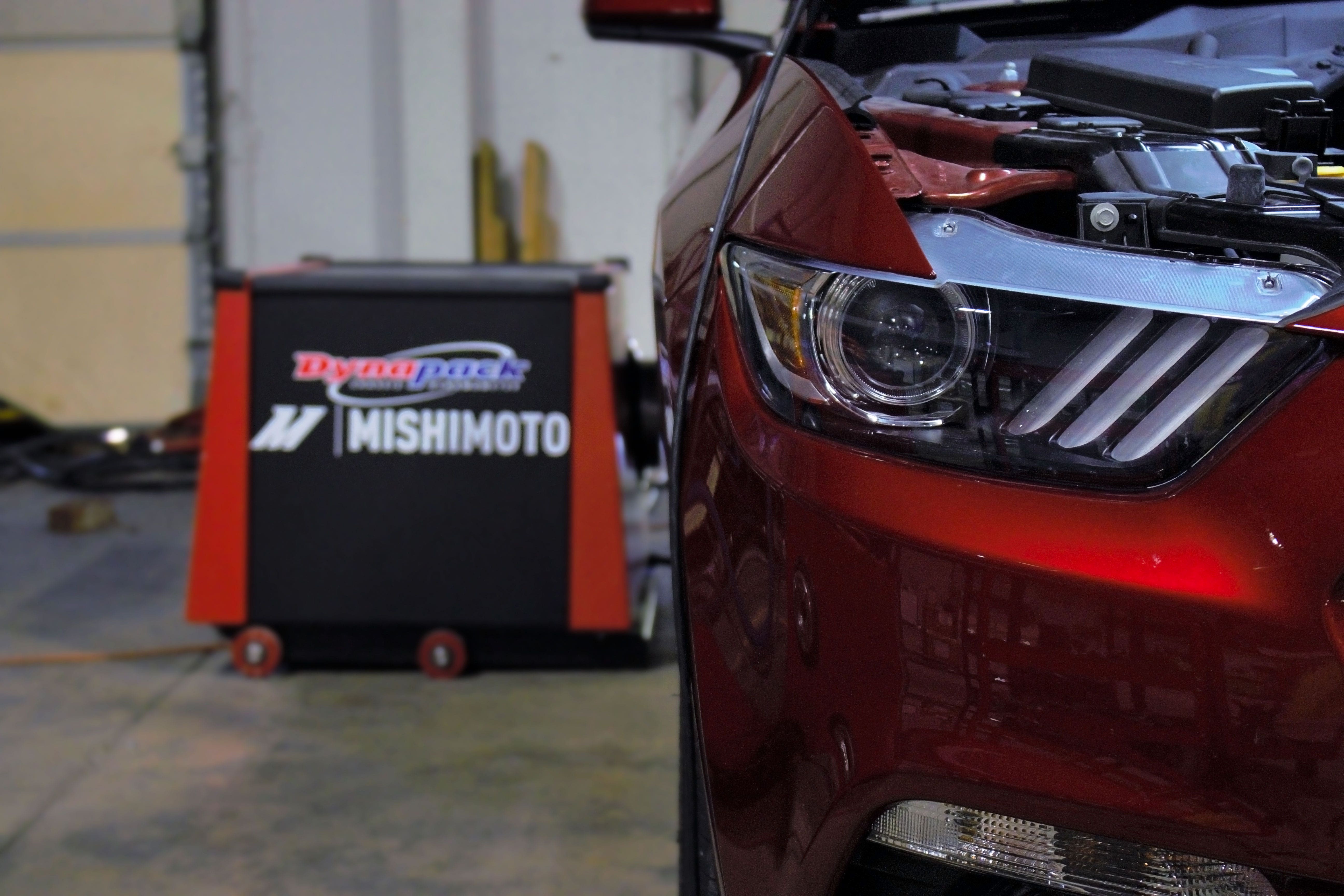
The GT looks ready!
We wanted to look at several things in this car. We know a few intake kits out there require tunes to run with this S550. One of our priorities was to ensure that this this intake would safely run on a stock tune while making reliable and repeatable power gains. This gave us a direction as we dove into development. We knew that closely monitoring the behavior of the air-fuel ratios (AFRs) throughout the progress of this design would be important. To get accurate numbers, our engineers wanted to look at how our prototype performed at highway speeds. Real-world testing is just as important as putting the car on the dyno.

Our prototype getting ready to get on the road!
The data from this testing came directly from the onboard-diagnostic (OBDII) system. One of our engineers installed a nifty third party software app on their iPhone; it gathers running fuel trims, intake air temperatures (IAT's) and ambient air temperatures. We simply connect this device to the OBDII port and then log runs! We used the same type of software to get the data for our another intake project (the 2016 Ford Focus RS), so feel free to check that out!
Fuel Trims and Road Testing Explained
I mentioned that we monitored fuel trims, so let's briefly talk about what they are. A vehicle has to keep the ratio between air and fuel within the engine balanced. A playground teeter-totter is the best way to visualize this. If we put air and fuel on either end, it is the engine computer's job to keep the balance as level as possible during the constant (and sometimes violent) changes in throttle input.
This is all measured in short-term fuel trims (STFTs) and long-term fuel trims (LTFTs). The STFT is a measure of the fuel mixture at any given moment while the car is running, whereas the LTFT measures what is happening with the mixture over a longer period of time (usually predetermined if you are recording those numbers). Our engineers recorded fuel trims with the car at idle and while on the go, with the rpm set at 2,500 at a speed of 60mph. This GT has tame fuel trims that did not change much during our testing when we looked at the stock intake versus our prototype. This is good news! It means that AFRs will be safe with our intake and won't give you any issues.

Getting some information from the GT has never been so easy!
This was also a great time for us to monitor the IATs. A common point of consideration for many S550 owners is how high these IATs can get, especially at idle. It is not going to be easy to combat IATs at idle. According to our research, that issue is hard to get around, and although our airbox will be powder-coated black and fully enclosed, it will be metal, so we can't ensure that it will improve idle IATs over stock. However, we did slightly improve the efficiency of how the air is directed into the kit, which did good things to our IAT numbers when at speed.
Our baseline road testing yielded IAT numbers averaging 95.8˚F with ambient temperatures at 89.2˚F, which is about a difference in 6˚F. Our prototype performed similarly, keeping the at-speed temperature difference close to what our stock runs yielded. Considering our prototype is going to be metal, this already tells us that we are outperforming the stock intake performance when it comes to the increased volume of inbound air. We also plan to use a plastic injection molded MAF housing as opposed to the aluminum version our prototype uses, which has the potential to do even better with the temperature!
Road testing for fuels trims is important, and we understand that now. When developing an intake, it is also crucial to understand that initial gains and learned gains are two totally different things. For example, let's say we have an awesome intake design ready to be installed on a car; we dyno test it and see some great gains. Awesome! It's ready to be sold and advertised with those incredible gains right? Well, not exactly. When the car starts to learn how to adjust itself to the larger amounts of air being brought into the motor, it starts to compensate and balance the air-fuel ratios on its own. This generally results in a drop in horsepower after a few hundred or even thousand miles of learning. For example, a gain of 10 hp initially seen from an intake may not be sustained 2,000 miles down the road, because the car will relearn to cope with the surge of extra air. The performance is still improved, but the gains would realistically be dropped by a few ponies. This isn't bad, it's normal. All cars go through this process.

Data collection is always the fun part
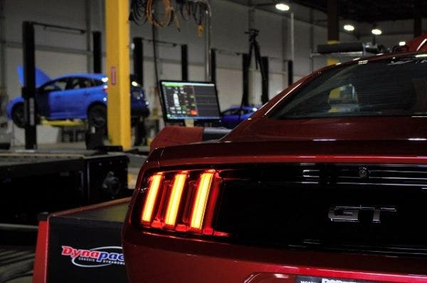
We did a fresh dyno run with this intake on the car to see how it would initially perform, and the gains were impressive; we saw peak gains hit the 30 hp mark! Since we like to be as thorough as possible with our product testing, we logged hundreds of miles with this intake on the car and then retested it on our dyno to get final numbers. Let's move on to some dyno video and results!
Sounds pretty great, don't you think? You can really hear the difference with the improved throatiness and aggressive engine tone. For fun, I even threw in a clip of a dyno run without the airbox lid.
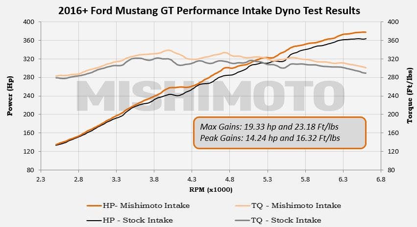
This data comes from an average of multiple runs after the car relearned with our prototype installed. We saw max gains of about 19hp and 23ft-lbs of torque. These are awesome numbers that our engineers are proud of, especially since it was a consistent average gain throughout all of our runs. The plot shows that at the very early side of the power-band, we make some slight improvement on the curves, but it's not very noticeable compared to when it really picks up at around 3800 rpm. After that, the gap between the stock and our prototype stays spaced.
Pressure Drop

Here we have our engineer running our intake on the flow bench
If you don't know what pressure drop is, no worries; I'm here to help! Pressure drop is measured by the amount of resistance the air has to meet when it is flowing through the air filter. Imagine a vacuum cleaner with a hose attachment. If you turn it on, you can feel the air being sucked through the opening, but what happens if you place a sheet of paper flat in front of the airflow path? The vacuum cleaner will have to work much harder to do its job. Now, let's say you removed that paper and increased the hose diameter; the vacuum would not have to work as hard to bring in even more air. Intakes work in a similar fashion. A pressure drop happens when you lessen the restrictions to the airflow as it enters the intake system.
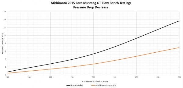
When it comes to intakes and pressure drop, the lower number always wins because resistance is decreased. In the chart above, you can see that as we increase the CFM number using our flow bench, the plot moves up, meaning as more air is brought in, the more resistance it will face.
We saw a total pressure drop of 47% over stock. This means that we are improving the pressure drop that not only the filter sees, but as an entire intake system by a large margin over stock. Think of it this way: Incoming air faced with less resistance is a win-win for everyone!
What's Next?
Our tribe of engineers have spoken. We are going into full scale production with this kit. When we receive a production sample, we can install, inspect, and review it before we start shipping these to our warehouses. When one comes in, I'll be sure to snap a few pics and show everyone. For now, I hope our prototype will hold you over.

Final product coming soon!
I hope you enjoyed reading through this lengthy update. Stay tuned for more!
-Diamaan


