Stranger Danger - Baffled Oil Catch Can R&D, Part 2: A Canned 'Stang
Our engineer has advanced engineering tools at his disposal. Arguably, one of the coolest in our facility's arsenal is our scanning device. This high-tech piece of equipment allows our engineer to scan anything in 3D space into a computer file. The file is then uploaded to a computer so the engineer can design whatever they want within the 3D space they scanned. The fine-tuned hands-on engineering element is still there, it's just done a lot faster and just as accurate with this machine. We call this contraption the Faro Design ScanArm and we have a full, detailed writeup on how it works. Cool technology aside, let's get into the design of this catch can kit.
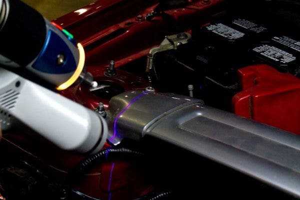
The scan-arm at work!
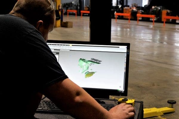
A peek at the resulting image file
Every vehicle's engine bay components experiences vibration. It's automotive nature. But catch cans can't be subject to this rigorous shifting because the lines to each can port must remain in place, so we need to find a spot on the chassis that will have the least amount of vibration. The strut tower is a great spot for secure fitment. Since the strut bar stands as a symbol for rigidity and stability in comparison to other components, the part of the chassis that it mounts to became the prime location for our project, and thus, the first place the engineer scanned.
Mounting brackets for a catch can project are basically wild cards. You really don't know what they will look like until the initial designs have been finalized. We had to use precise equipment because we knew that there needed to be a good balance between material thickness, strength and clearance below the strut bar. All cars may not have the strut bar, but for those who do, we want to make sure you can still use this kit. Once the bracket is designed, we need to fabricate a prototype. In the past, a long and arduous process ensued to make a physical prototype. It involved a lot of calculating, measuring, cutting, fitments, re-fitments, re-cutting - you get the idea. It was a manual process. While we were still able to produce products with spot-on fitment, those days are now behind us. We've got a machine built to pump out designs like this in mere minutes. It's called a waterjet. As the engineer finishes his CAD (computer-aided design) part, he sends the file to our fabricator, and that file is uploaded into the programming of this large machine. The waterjet, using a mixture of water and an abrasive material, can shoot liquid out at over 30,000 psi to cleanly slice through large metal sheets, cutting out what is on the file with pinpoint accuracy.
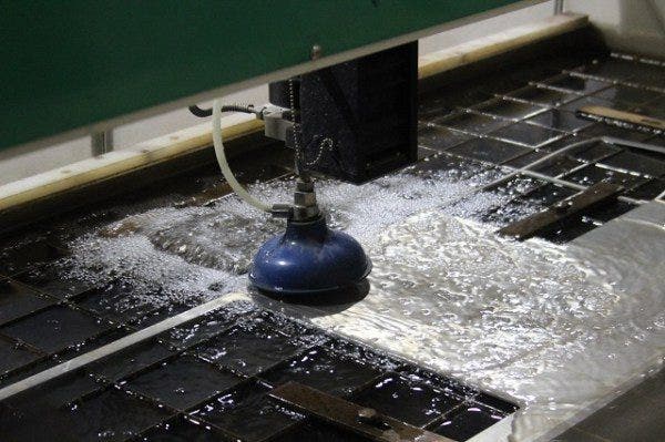
Our shop foreman, Mike, helped put together a video (see below) of the waterjet in action. It's an informative breakdown of the machine and how it operates, which includes some innovation on our part with the use of a Mishimoto cooling system!
After the waterjet process is complete, the raw bracket is bent into the proper shape and slapped onto our loaner Mustang GT.
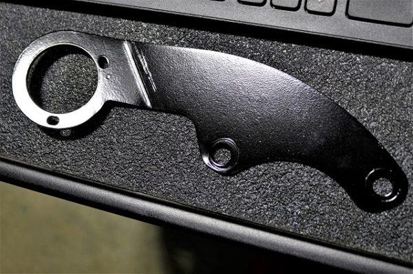
Here's the bracket, freshly cut and painted!
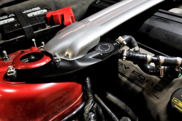
Perfect fitment!
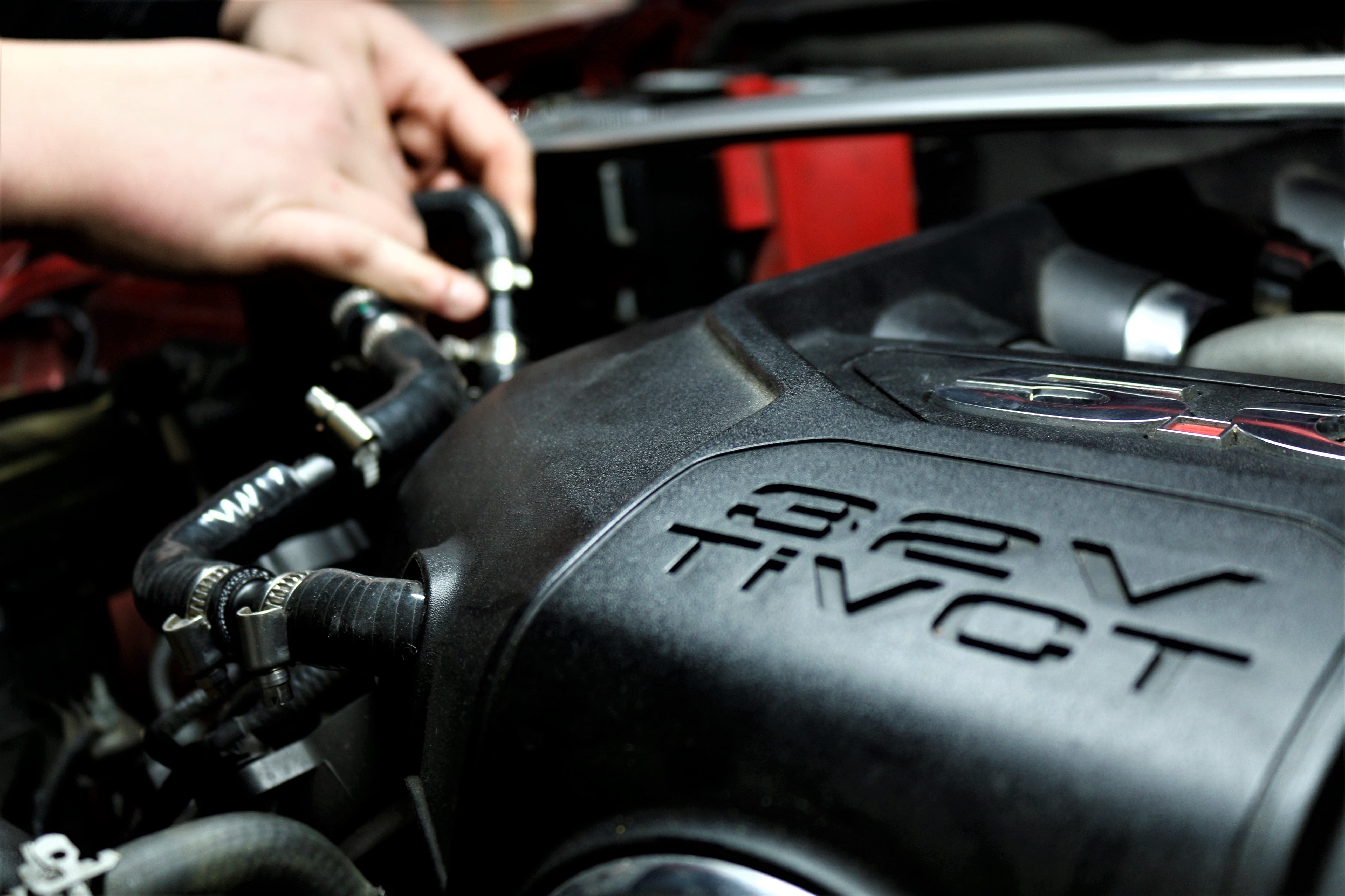
The hose routing is an approximate placement and for now, it will work. The car needs to be driven for a few hundred miles to see how our catch can setup works. The next time we bring this Mustang back in, we will show you how much oil will was caught.
-Diamaan
