Civilized Pipelines: Intercooler Piping R&D, Part 2: Fabrication Magic
Enlarging charge pipes for your turbocharged engine must be a detailed and accurate process. Think about it. It's not like companies make a charge pipe kit that is well-designed, well-documented, direct-fit and requires no modification to, let's say, a twin-turbocharged LS1 V8 engine fitting 1995-1998 Nissan 240SX's. You are going to need a fabricator for that, a very good one. It will be a one-off kit specifically for the car brought into the shop, not able to be mass produced due to the unique setup.
You can't design good intercooler piping that fits a particular application for wide-scale production willy-nilly. Without the use of the proper tools, time, and R&D, the resulting product will be met with negative feedback from the surrounding automotive community. With the overall tight engine bay clearances of this 2016+ Honda Civic 1.5L Turbo, working around the space to design piping that will fit with a larger diameter than stock is a priority. Even slight miscalculations in the design parameters will result in ill-fitting pipes. I've already shown you that the factory piping isn't necessarily the simplest, so to make a great product, there are steps to take.
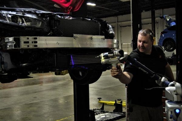
Lead engineer working on scanning the front of the car into a computer file
We have a nifty tool to scan tricky design space into a computer file, easily manipulated by the engineer to create whatever part they want with pinpoint accuracy. Our engineer decided to use our scan tool for these pipes, but here is where it gets interesting.
These pipes are made much faster and more accurate by scanning
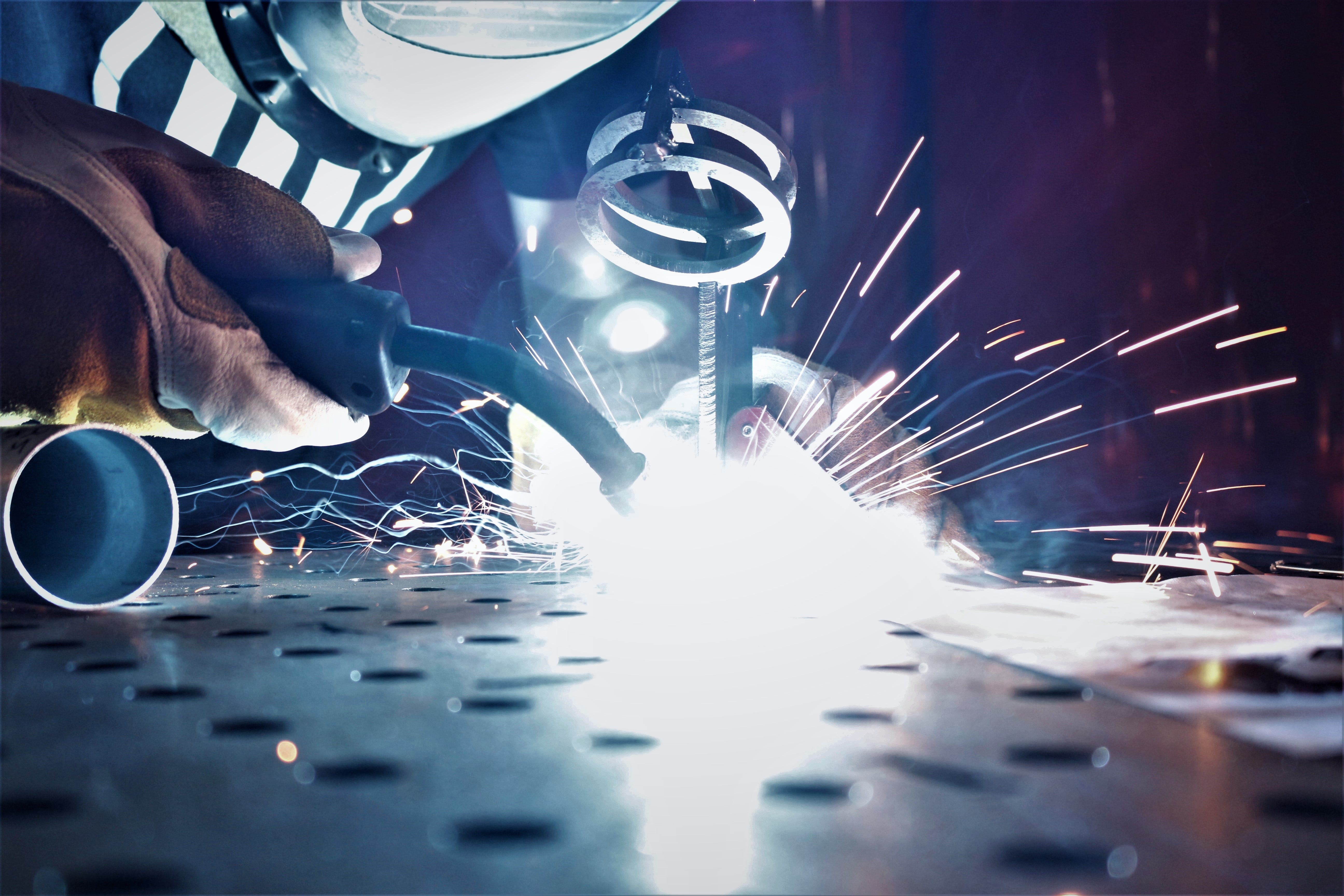
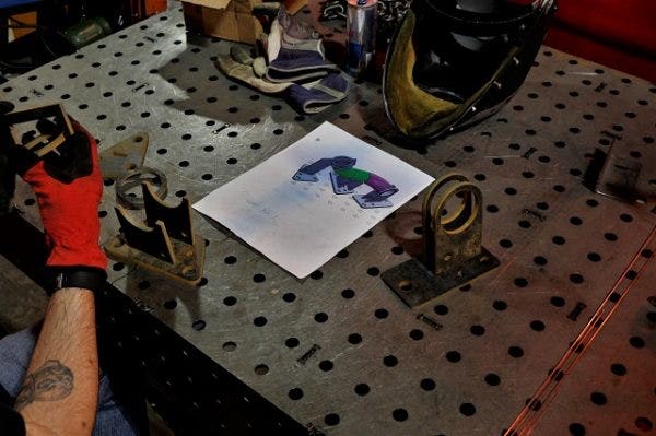
A common industry trade when it comes to fabrication is the design and construction of a "jig" for automotive piping applications (things like intercooler piping, exhausts, downpipes, etc.). This jig is essentially a basic framework for piping structure. The pieced together jig is created in a CAD (computer-aided design) program by the engineer and printed out for our fabricator, giving an idea of exactly how the pipe will look. Each fixture is a part we cut out using our waterjet. Once all pieces are cut and assembled, it's a matter of fitting the proper size, length and angles of the pipe sections through the jig and welding it together. We've done this for previous intercooler piping and exhaust projects, but this was my first time seeing the entire process from start to finish, up close. It's like watching a form of automotive scaffolding take shape.
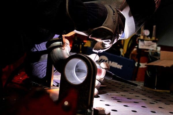
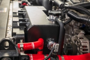
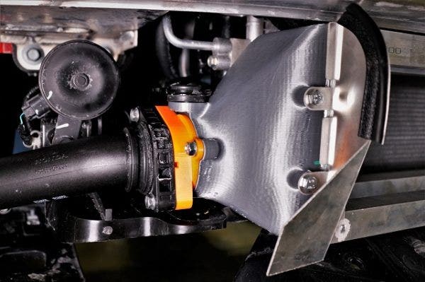
The lower part of the cold-side pipe mounted up
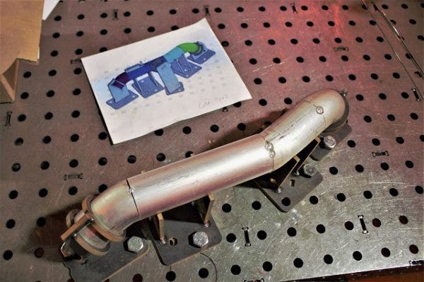
Here is a complete, tacked together piece of the hot-side pipe
With both pipes finished, it's time to move on to how we plan to connect them to the intercooler. That might sound simple and mundane, but it's quite the opposite. Honda has connected their factory piping to their factory core using flanges sealed with inner O-rings, a relatively uncommon feature in factory turbocharged applications, and this presents a problem.
For either our upgraded intercooler core or intercooler piping to attach to the end tanks, we need adapters to accommodate the different sizing. We want everyone to be able to use our intercooler, so the core will start out having adapters to work with the stock piping. The upgraded piping is where fitment will be a challenge.
Check out this sneak peak!
-Diamaan