Civilized Pipelines: Intercooler Piping R&D, Part 1: Design Plans
Turbocharger compressors like denser air, which is why us car enthusiasts joke about how, although the winter is the motorsports off-season, it's peak "boost" season. Cars with forced induction love the colder, denser climates because by driving in colder weather, the turbocharger or supercharger gets fed a bit more air than in warmer weather. That's why you might feel a harder punch from the gas pedal in the middle of a freezing Chicago December compared to a Daytona Beach July.
Since we don't all boost happily in the Siberian Tundra, the way to replicate this effect is by finding a way to supply more air to your method of forced induction. One way to do so is by making your intercooler piping or charge pipes larger. Larger pipes allow more airflow, which translates to more power. Our lead engineer for this entire intercooler project is very familiar with this idea, before creating larger pipes, we must first evaluate the stock pipes - hot side and cold side - to know exactly what we are dealing with.
The Hot Side

Aerial view of the hot side pipe's rubber portion

Bottom feed pipe to the intercooler
The hot side intercooler pipe is the side that connects the turbo to the intercooler and is where the hot air enters the core to be cooled. The construction here is fairly simple. There is a rubber hose that attaches directly to the turbo, and that piece connects to the rest of the plastic section leading to the intercooler. We want to eliminate this inconsistency. There are two connection points where airflow needs to travel through to get from the turbo to the intercooler, and we want to reduce that to one. Doing this will provide a smoother and larger pathway for the air to travel, boosting performance.
We plan on replacing the lower section of the piping with steel reinforced, silicone tubing, allowing for minor flexibility while staying rigid enough to prevent collapsing under vacuum. We will fabricate the rest pipe from aluminum. Designing our pipe this way is superior to having one long continuous piece going from the turbo to the intercooler, which would cause extra stress on your charge pipes due to the engine movement.

Full view of the factory hot side intercooler pipe
So, now we have a clear line of sight for how to improve the hot side pipe. It's the cold side, though, that happens to be the tricky side.
The Cold Side
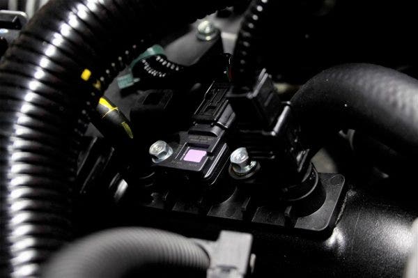
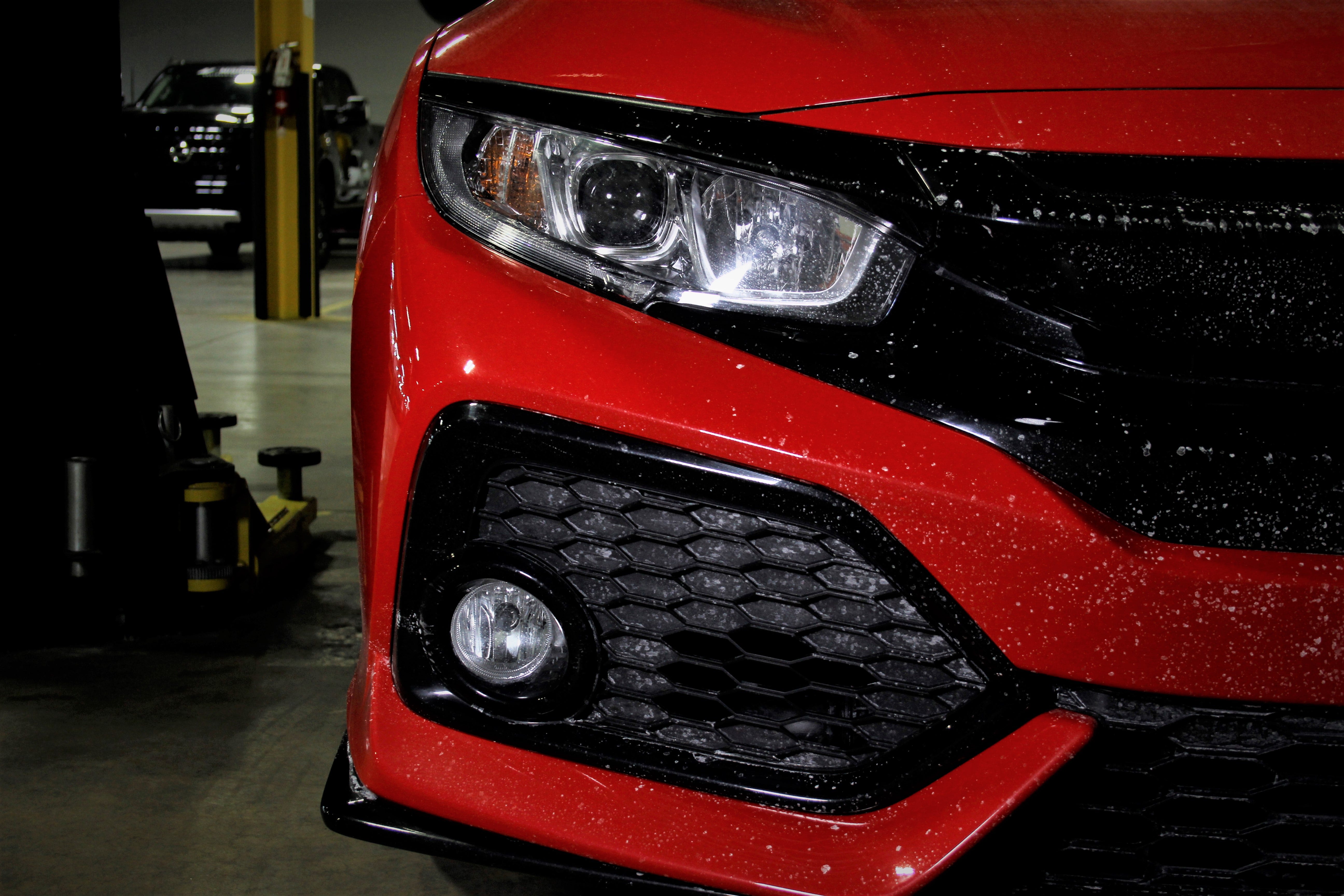
The cold side intercooler pipe is the side that connects the intercooler to the throttle body, delivering cooled air from the hot side of the system. On this Civic, the cold side has three ports directly on the pipe for a temperature sensor, a MAP (manifold pressure) sensor and a vacuum line. Having these attachments directly on the pipe provides a bit of a challenge when it comes to designing our pipes. Our engineer will probably have to design a machined part that will be welded on to the pipe for that to work. In addition to that, this pipe uses a bracket to securely anchor itself in place on the engine. We are still working out how we want to incorporate that bracket as well since it's important transfer as little movement to the pipe as possible.

Stock bracketry and sensor attachments
The lower section of the pipe also has an accordion section to give some flexibility in the event of the engine moving under torque. While the idea here is solid, the inconsistent surface through which the air must travel needs to be smoother. We plan to remedy that by not only increasing our pipe diameter here, but also having a long silicone section to act as a coupler, connecting the aluminum pipe to the turbo.

Cold side end tank fitment
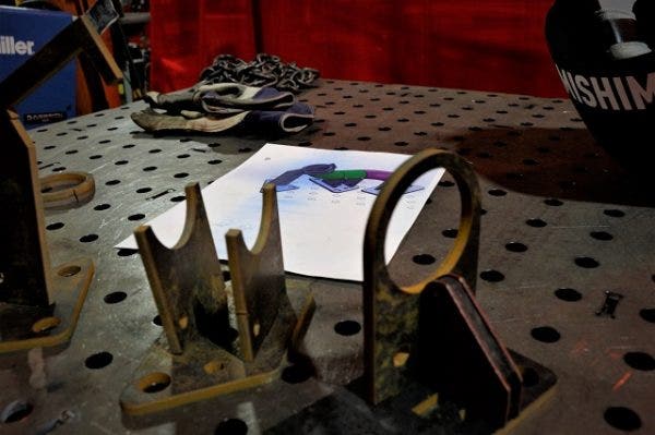
Our prototype pipes will be designed and fabricated in-house at our R&D facility. For an accurate design, our lead fabricator has an interesting process to make a physical copy of whatever our engineer finalizes in his computer-aided designed. It is a process we have used in the past and yields efficient, quick and precise prototyping that is cool to observe, and should make for an entertaining read in the next update. Stay tuned!
-Diamaan
