Cool Air For the EcoBoost - Intercooler R&D, Part 8: Test Fit and Dyno Data
Greetings, folks, and welcome to the post you've all been waiting for! We've made a ton of progress lately on the Mishimoto 2011-14 EcoBoost Intercooler, so I am happy to present you with a detailed update. As such, I will cut right to the chase so that you can see what we've been working on.
Oh, and I almost forgot - we threw this thing on the dyno and I've finally got some numbers for you! Before we get to that, let's take a look at how this intercooler looks in its final guise and see how it fits in our 2013 test subject.
Ford F-150 EcoBoost Intercooler; Factory Review
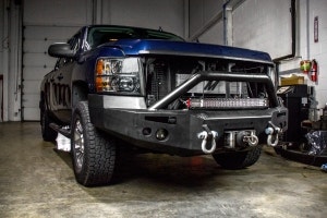
As a refresher, this is the factory tube-and-fin unit that we are replacing. You can see that it is rather small and as a result, does not make very efficient use of the space behind the front bumper, which is ample, but unconventional in shape. Check out our first blog post in this series to learn a bit more about the Ford EcoBoost intercooler and cooling system.
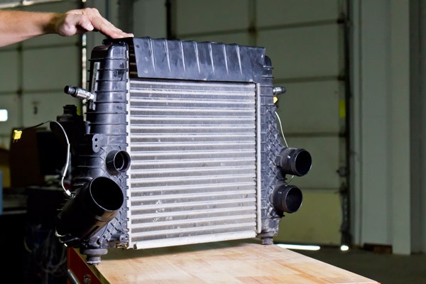
The stock 2011-14 F-150 EcoBoost intercooler
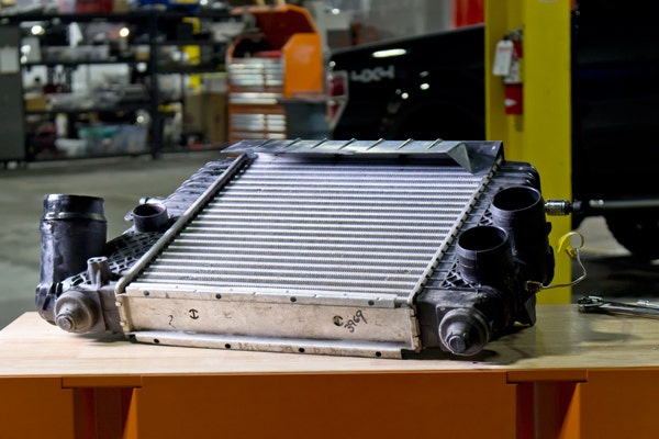
From this angle, you can get a pretty good look at the thickness of the factory intercooler
Mishimoto's EcoBoost Intercooler
You've seen the 3D-printed mockup, and your eyes have beheld the sight of our 3D models, but it is time to reveal the final product. Though it looks quite dashing in photographs, it's even better in person. This exchanger occupies a decently larger volume of space than factory and is of very rotund construction. Its hefty, imposing design conveys an aura of strength and quality to match that of the F-150 itself. Let's take a look.
The Mishimoto 2011-14 F150 EcoBoost Intercooler from the front.
Thanks to Steve's clever engineering, the intercooler incorporates a contoured design that allows for better fitment into the space behind the bumper. As you can see, this design element made it possible for us to increase the size of the heat exchanger by quite a bit, making it larger in every dimension than the factory piece.
As a refresher, an intercooler's purpose is to cool charge-air after it travels through the compressor side of the turbo. Though the turbo's compressor is commonly called the "cold side", it is actually quite hot given its close proximity to exhaust gases leaving the engine and its high rate of compression. As this toasty, pressurized air travels from the turbo toward the intake manifold, it passes through the intercooler, which transfers most of that heat to the ambient air, lowering charge air temps. Colder air is denser, meaning more of it can be squeezed into the cylinder, allowing for a larger combustion event. Our intercooler's large size provides more surface area for heat transfer, netting your truck lower manifold air temperatures and more power - and we've got the data to back it up! (more on that later.)

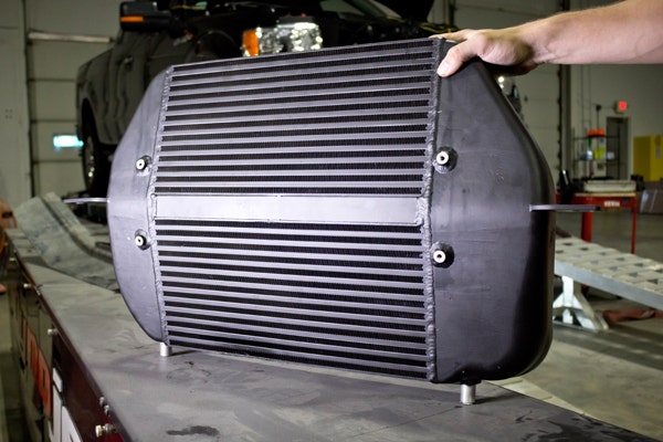
From the back of the intercooler, you can get an even better look at its contoured design. It is available in two colors: black, pictured here, or silver, which you'll see installed on the truck in the next section.
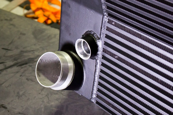
In this closer shot, you can see the bar-and-plate construction of the core, as well the outlet to the intake manifold. We've incorporated the factory quick-disconnect for maximum compatibility with other 2011-2014 EcoBoost parts. Also pictured is the mounting point for the bypass valve; 2013 and 2014 trucks utilize an intercooler-mounted bypass valve, which connects to this port via a quarter-turn thread. For those of you with trucks of a 2011 or 2012 vintage, we will include a plug to seal up this port, as the bypass valve on these trucks mounts elsewhere.
Installed Shots
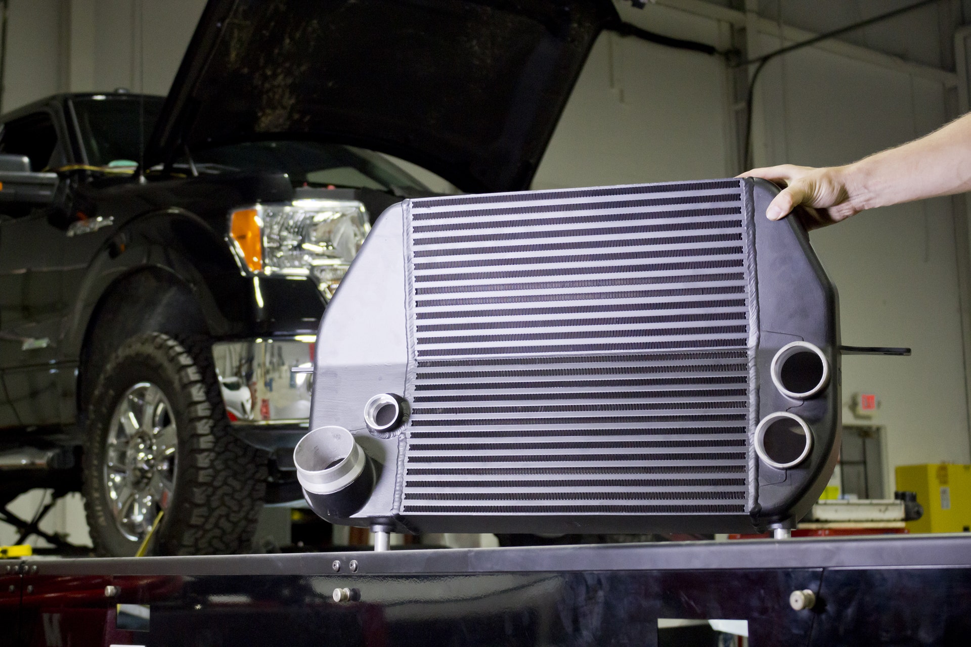
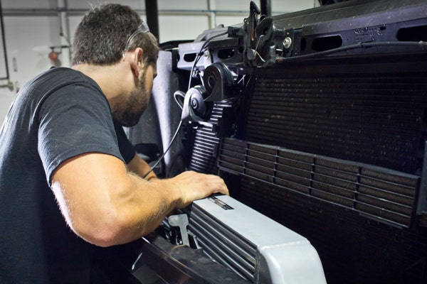
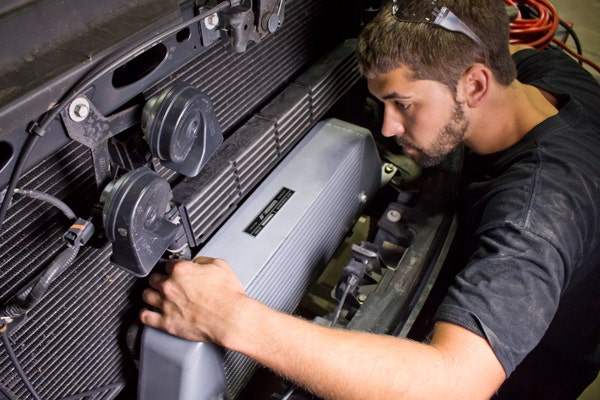
Now that you know how the intercooler looks by itself, I'll show you how it looks in the truck. Steve installed this part into our 2013 F-150 test vehicle in preparation for some dyno testing.

It helps to have an extra set of hands for this one! The install is super easy, but due to the size of the core and the shape of the space it occupies, I had to put down the camera for a bit to hold the intercooler and prevent it from dropping past its mounting points and turning Steve's face into a pancake. Once it was secure and we were certain that it wouldn't fall through, Steve torqued the last few bolts and we were ready to test.
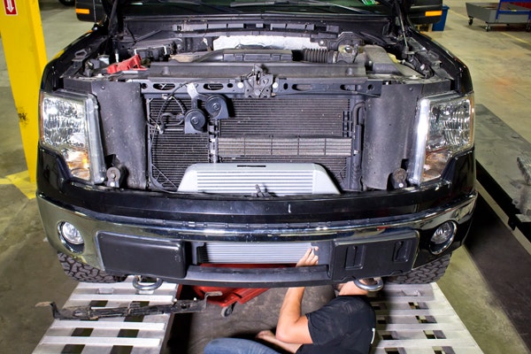
This last shot is particularly good at illustrating the size of the core and how it makes such efficient use of the airflow in front of the truck by extending above and below the front bumper support.
Now that you've seen how the intercooler looks and learned some more about its features, it's time to take a look at the numbers. I think you'll agree that they are even prettier than the photos!
Dyno Testing Overview
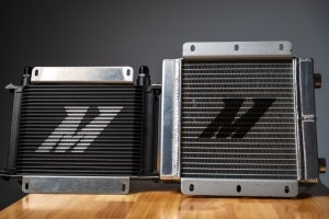
Our design process for this particular intercooler involved testing two different core designs. There are many attributes of a heat exchanger core that affect the way heat transfer occurs, and the internal passages of the core can impede or facilitate flow, which has an effect on pressure drop, so it is important to test multiple core setups in finding the right design to maximize efficiency.
We know that many of you plan on tuning your vehicle's ECU to optimize the benefits of your particular upgrades, so we wanted to test our intercooler using both the stock tune and a performance tune to find out the true potential gains from this part. We worked with Innovative Diesel Performance in Elkton, MD to come up with a custom tune to get the most out of our intercooler.
Choosing a Core
In testing the performance of an intercooler, the two most important independent variables to consider are charge-air temperatures (obviously) and charge-air pressure. There is commonly an inverse relationship between these two variables at the margin; that is to say that at a certain point, optimizing an intercooler for cooling requires a compromise in pressure drop. As you can see below, with both cores that we tested, we achieved better cooling AND a better pressure drop when compared to stock, thanks to our large intercooler design.
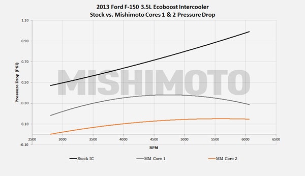
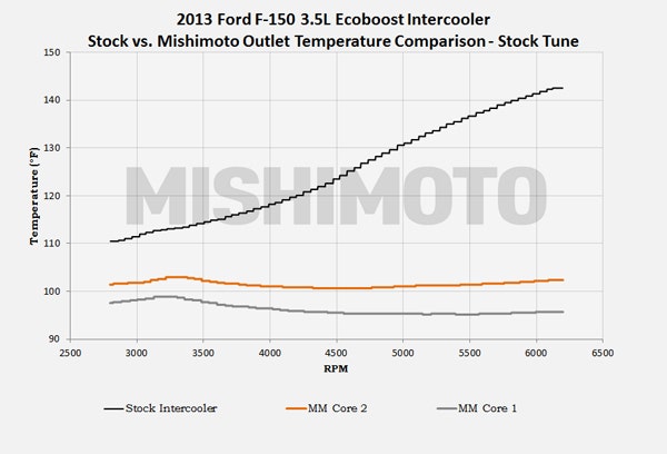
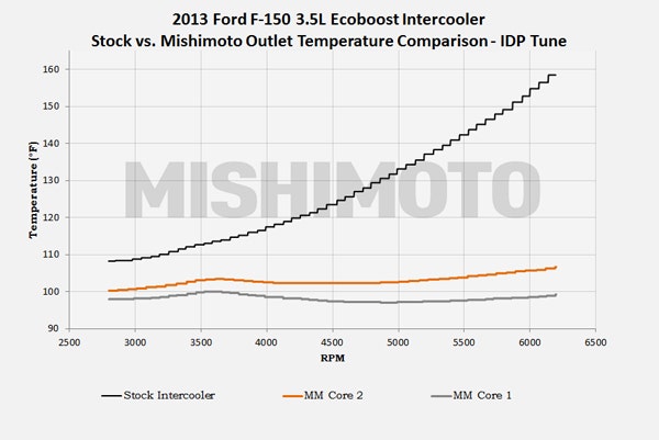
As you can see above, core 1 performed better in lowering temperatures, but core 2 exhibited a slightly more favorable pressure drop. Both outperformed the factory intercooler in each metric, so we decided to proceed with implementing core 1 into our design to maximize power gains. Speaking of power gains, let's check them out!
The Moment You've All Been Waiting For"
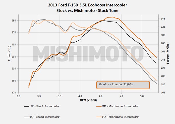
In this first chart, we used the factory tune and compared our intercooler to the original equipment. Each intercooler was run on the dyno five times and the average of each configuration was taken. As you can see, the gains are largely favorable throughout the power band, particularly on the high end. Let's see how we did with our custom IDP tune.
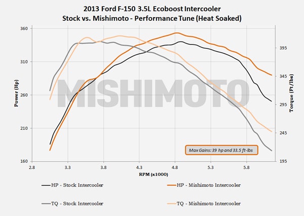
For this test the truck was run 5 times with only one minute of cool down between each pull. This test was performed to simulate heat soak. The final (fifth) pull for each intercooler configuration is shown in the dyno chart above. It is very telling to see how power gradually tapered down with the stock intercooler in place, but once the Mishimoto cooler was installed, power was barely affected, even once the intercooler was completely heat soaked. Tuning the truck's ECU really unlocks the full potential of this intercooler, realizing maximum gains of almost 40 horsepower!
What Now?
I know this one was longer than usual, so thanks for sticking with me. I hope you are as happy with these numbers as I am! Stay tuned, as the time is coming very shortly for us to initiate a discounted pre-sale.