Trickle Down Power - 2016+ Infiniti Q50/Q60 3.0T Performance Intercooler R&D, Part 3 - Prototyping and Preliminary Testing
Evolution for us living organisms is an arduous process. It's a generational operation that can take millions of years for adaptation or improvements to implement fully. Luckily though, we've evolved to the point where our tools and tech reduce the evolution process to our performance machines to a fraction of the time. As a result, we're implementing them in our Q50/Q60 intercooler development.
When we last left off, our prototype intercoolers were a plastic 1:1 scale model of our new design, specifically 3D printed for a real-world fitment check before starting our production. The trouble is that even with the advancement in technology, manufacturing is still a lengthy and costly process, especially when it comes to casting aluminum. Being the sticklers that we are, we wanted to ensure that our intercoolers would perform up to our standards before churning out hundreds of units without slowing down our development process. So, we decided to assemble a set of one-off working prototypes.
3D printing is something that we rely on here at Mishimoto since it's an ideal process for expediting our development process. While our printers aren't set up for it, this manufacturing method has advanced to allow for the printing of metal, which is ideal for our situation. Metal 3D printing doesn't require expensive tooling and is a much more efficient means of producing functional prototypes on a time crunch.
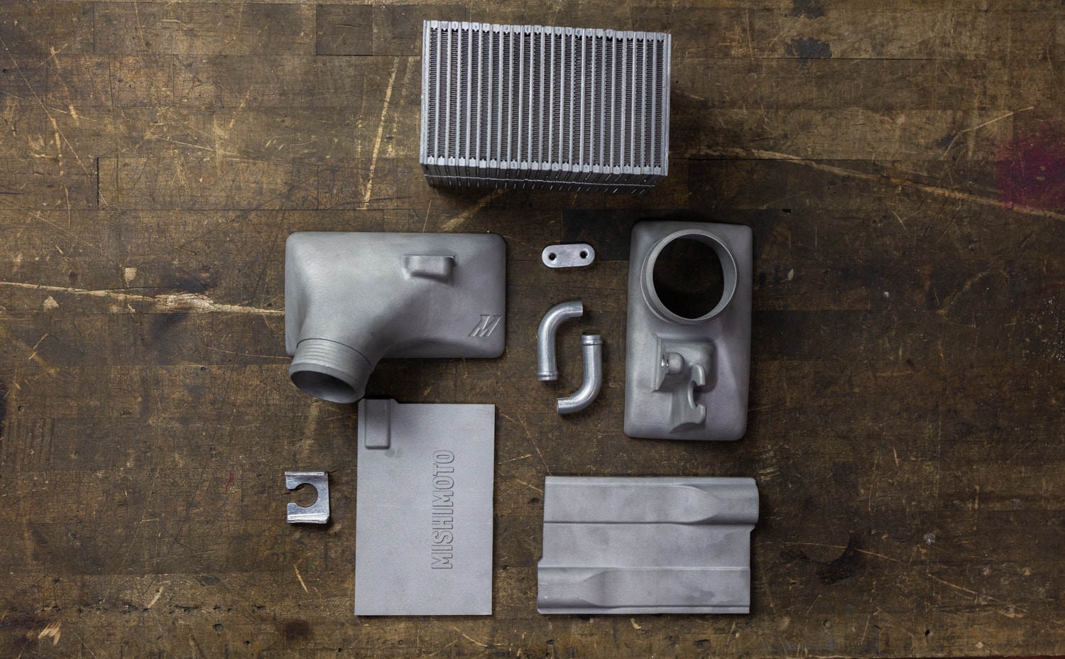
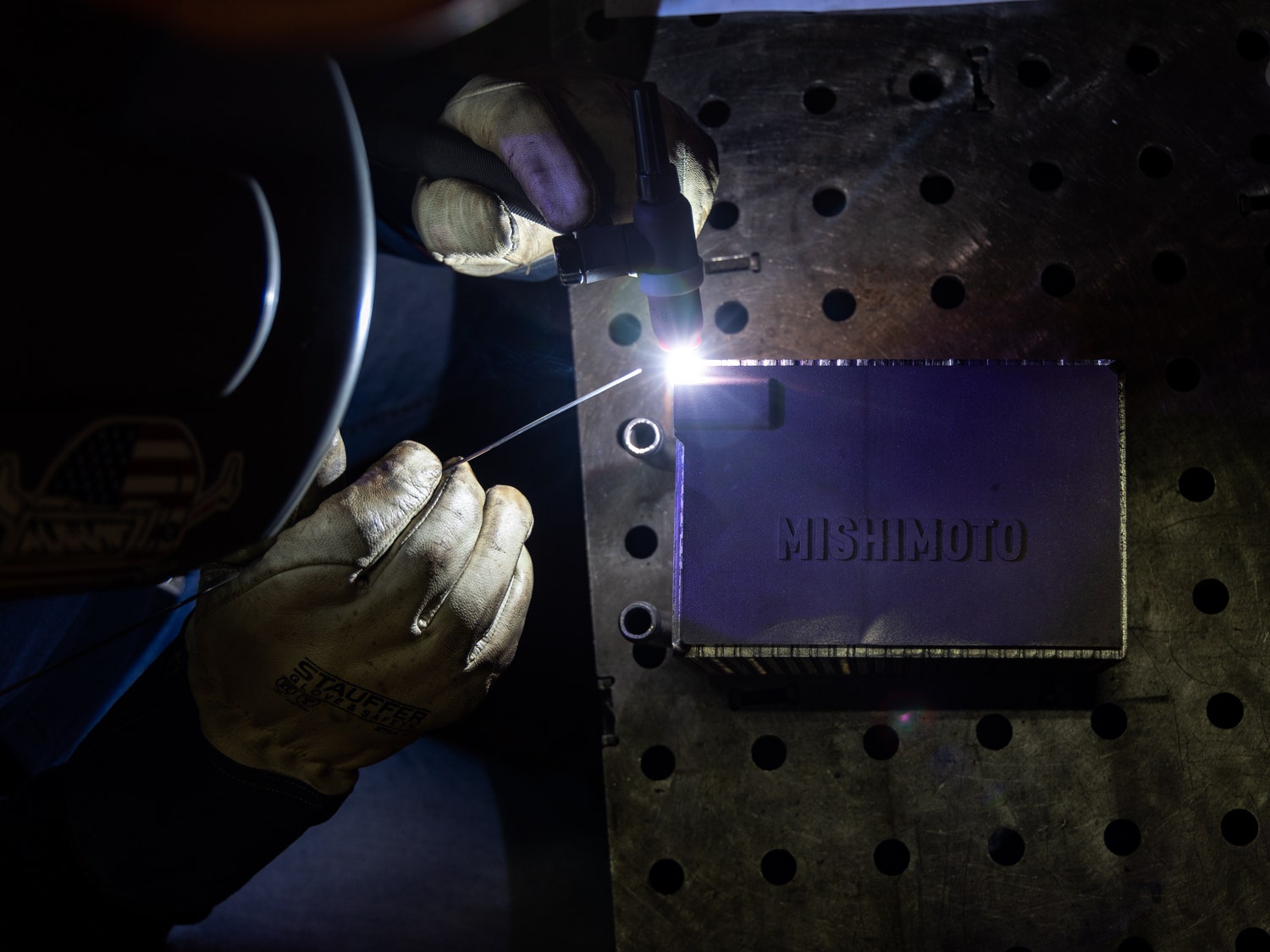
The Selective Laser Sintering, or SLS, process starts with adapting a 3D CAD design into an array of 2D cross-sections of the product. From there, the printing program directs a high-powered laser to melt, or sinter, the aluminum filament powder to the specific cross-section. After each pass with the laser, a fresh layer of filament is spread across the work area, and the material bed lowers in the machine to add the next cross-section. This process is repeated for each cross-section of the design until our new end tanks materialize from the bed of powder.
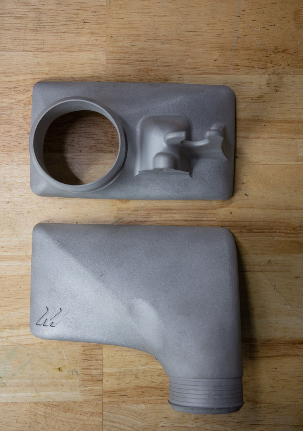
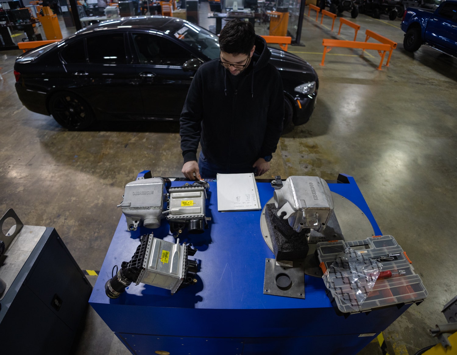
With the metal sintered, it was now up to our master fabricator, Mike, to fix the components together.

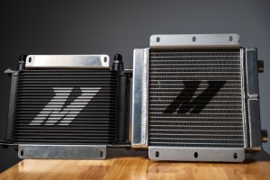
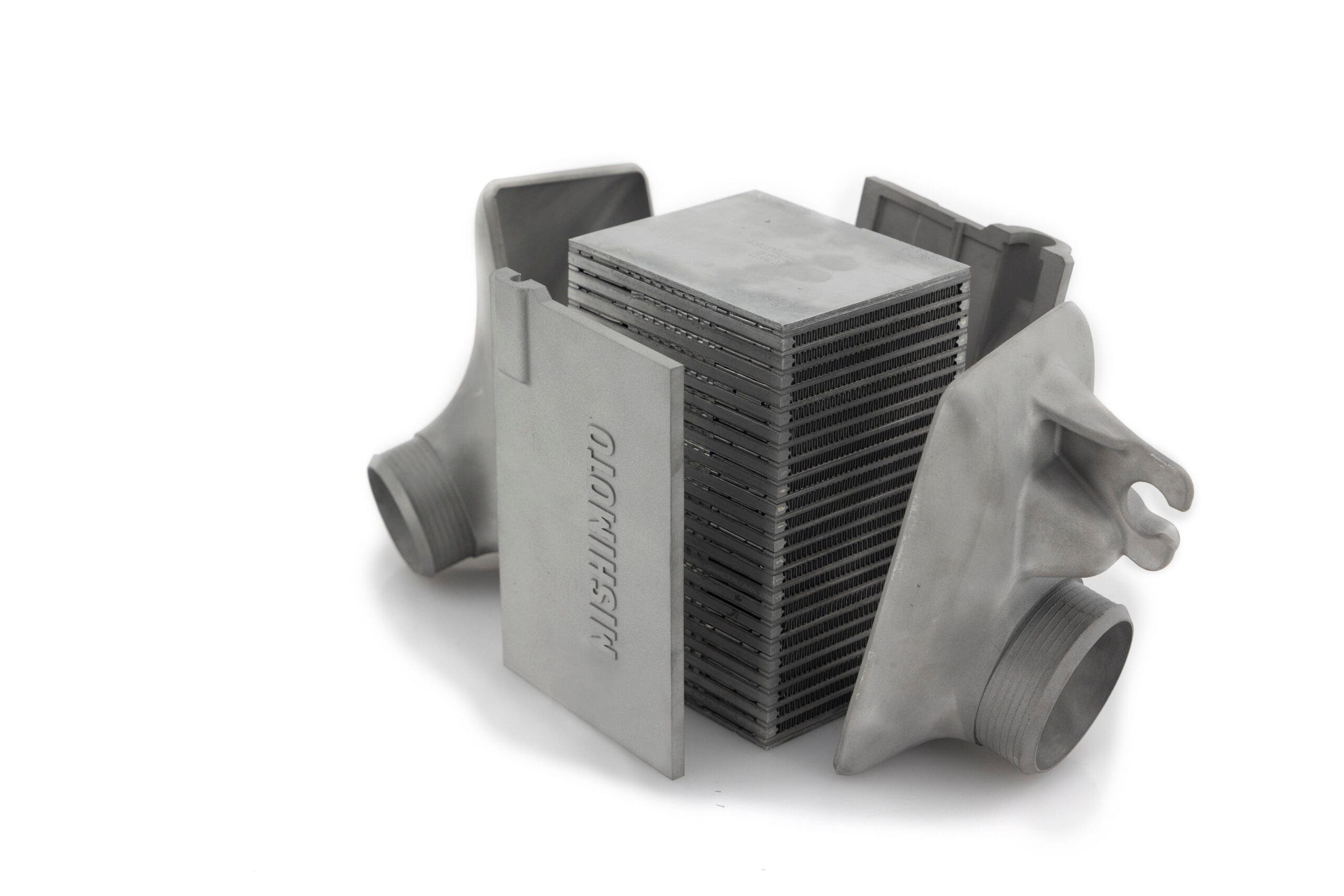
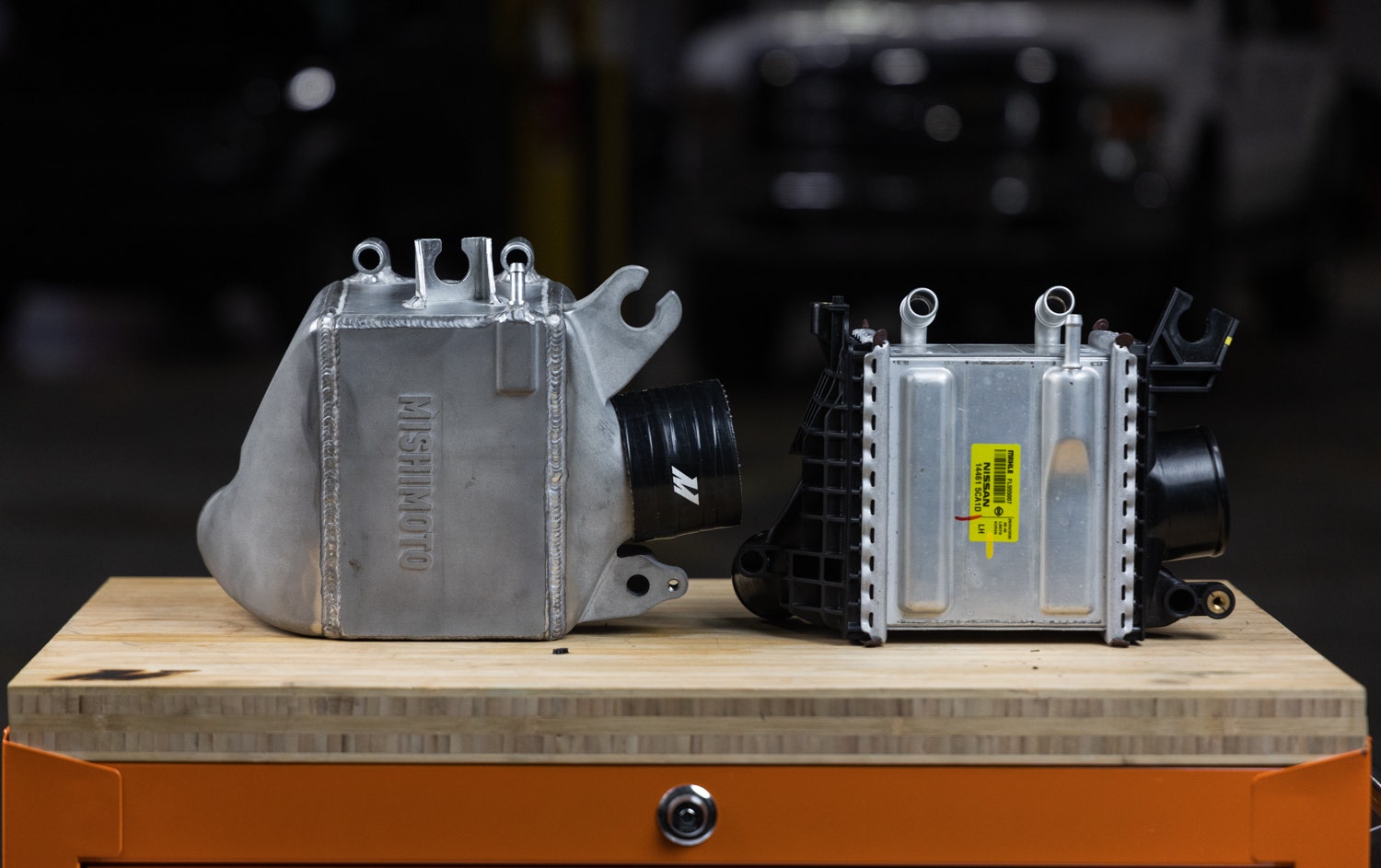
Our fully operational intercooler prototypes are complete thanks to some extra elbow grease on our end. Before we dive into our full round of testing, coming in our next post, let's take a look at how these physically stack up against the OEM units.
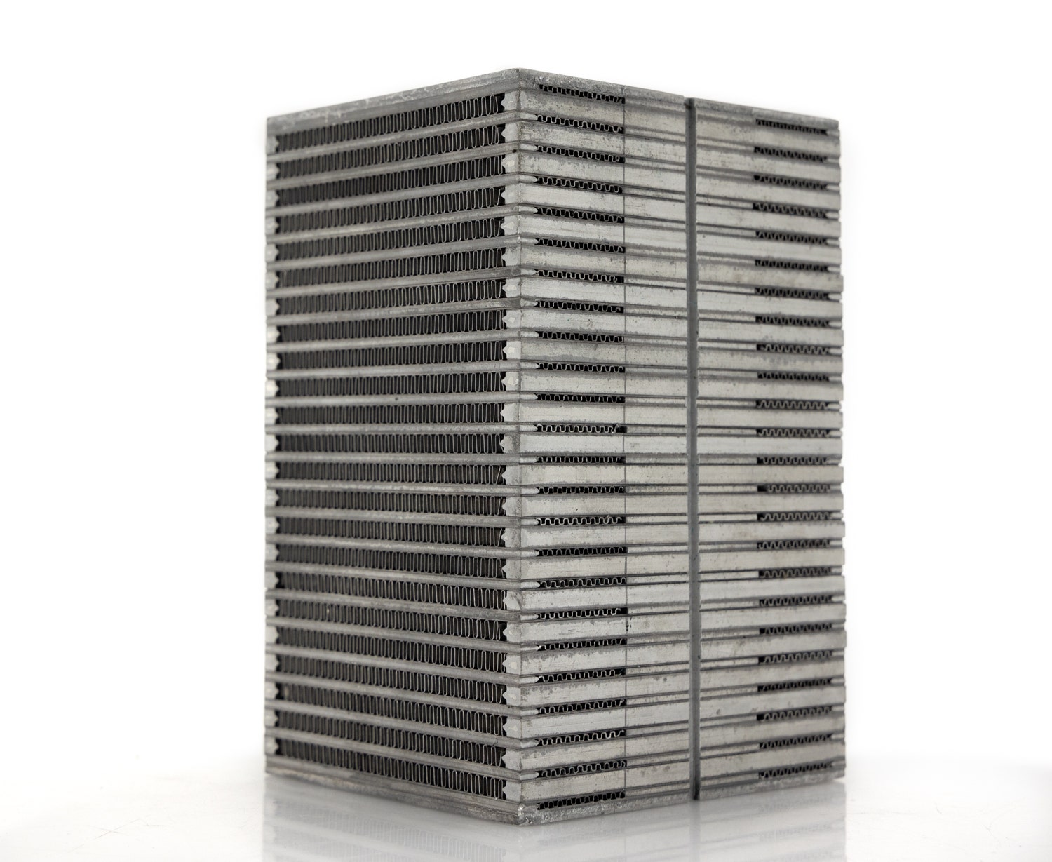
For starters, they've grown. As mentioned in the previous post, size still matters when improving cooling power, even in air-to-water setups. Specifically, the volume of our cores grew by 49.8% on each core which, combined with our updated bar-and-plate core construction, should result in more consistent intake air temperatures for your 3.0T.
Size is only half of the equation when it comes to intercoolers, though. The quality of air and coolant flow through the cores is just as important. We've opted to retain the OEM flow pattern for the optimal cooling gradient in terms of coolant flow. However, when it comes to airflow, our engineer wanted to ensure that these intercoolers kept up with the flow demand of tuned or big turbo vehicles.
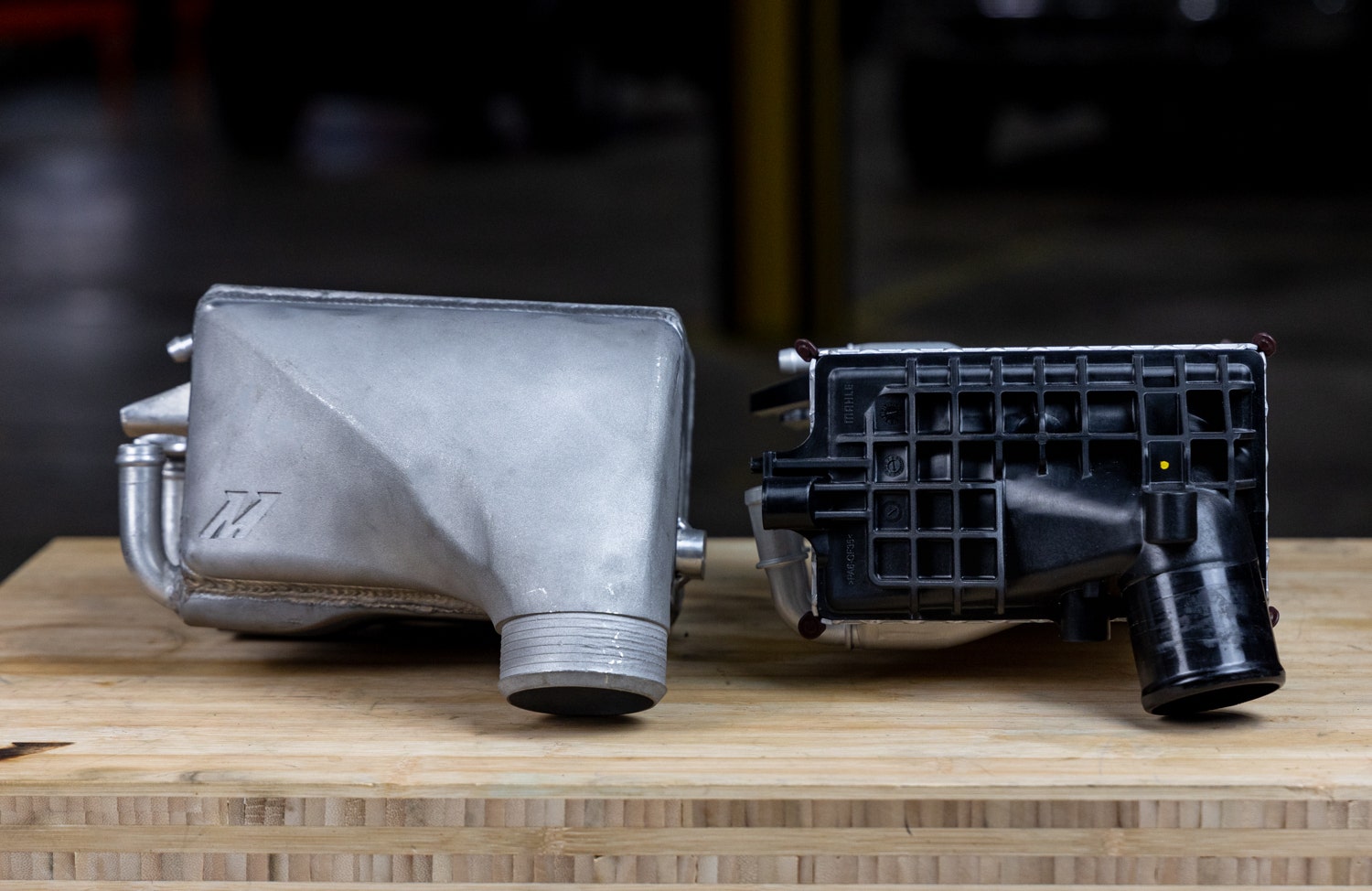
To start, and as you've already seen, the end tanks got a sleek makeover. But, again, size is the name of the game, with our inlet side tanks extending further into the depths of the engine bay. This longer reach also provides a more gradual and smoother transition from turbo to intercooler. Plus, we were able to increase the inner diameter of our intercoolers' inlets for a more free-flowing design. Our updated core design also features a revised internal fin design which reduces flow restriction on both sides of the intake plenum.
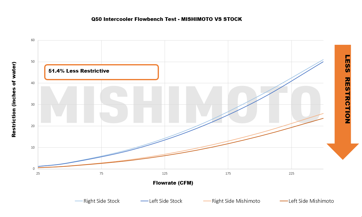
How much better do these flow, you ask? Well, to find out, Dave ran a series of comparison tests between our prototypes and the OEM intercoolers on our flow bench. This device can either push or pull precise volumes of air, measured in cubic feet per minute, or CFM, through each intercooler, which allows for an accurate comparison between the stock units and our design. Dave installed an array of sensors throughout each kit to pinpoint the areas that pose the most restriction and generate an overall flow reading. Since the amount of air flowing through these intercoolers will vary as you drive the car, Dave blasted a range from 0 to 250 CFM through the intercoolers to simulate the vehicle's entire powerband. Overall, we saw an overall 51.4% reduction in flow restriction in the intercooling system.
Even though mechanical evolution is vastly accelerated these days, precision still takes time to perfect. So we still have some ground to cover for now but stay tuned for our full dyno results coming soon.
Thanks for Reading!
-Nick