Lead the Charge - Performance Charge Pipe R&D, Part 1 - Stock Review and Design
"Supra" is a name that evokes all types of tuner fantasies. These days, it's more uncommon to find a MKIV Supra that isn't hugging the asphalt or pushing 800+ horsepower to the wheels. Modifying a Supra is an enthusiast tradition. When the A90 finally came along, plenty wanted to carry on that tradition. However, with more power, stronger bolt-ons are needed, which is why we're focusing on the GR Supra's charge pipe.
It's beyond old news at this point that BMW pulled most of the weight when it came to the development of the A90 Supra, basing it on the G29 Z4. The tag-team effort means that the MKV ain't no slouch in terms of performance and quality. Like any mass-produced vehicle, there will still be some shortcomings for the sake of cost.
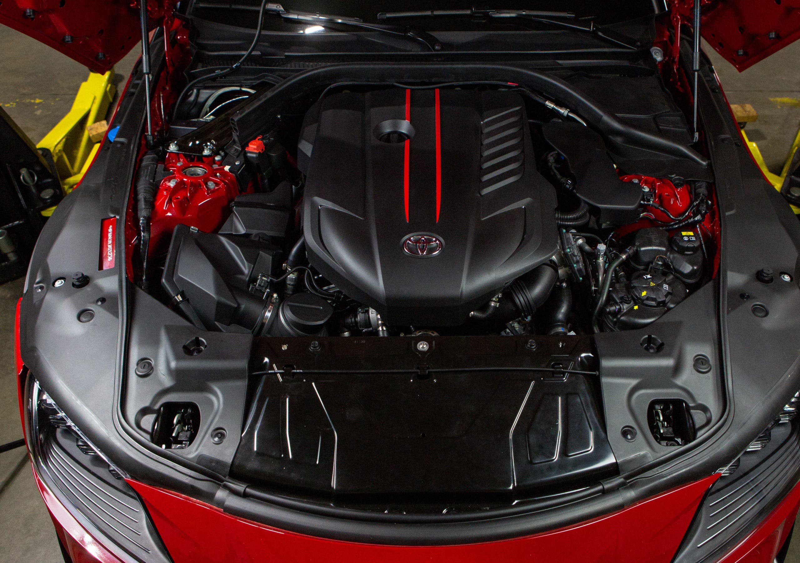
The B58 that powers the Supra is unique in that BMW integrated the air-to-water intercooler into the intake manifold. This union works wonders for reducing pressure loss by eliminating the cold side of the intercooler pipe system. The half that remains, known as the charge pipe, is responsible for channeling freshly compressed intake air directly into the intercooler. Since this is technically a BMW part, we're already expecting superior build quality, but we extracted it for proper examination anyway.

With the intercooler out of the vehicle, there were no surprises. BMW manufactured the factory pipe using plastic injection molding, form-fitting to the Supra's engine bay. Plastic is a godsend for OE manufacturers since it allows them to churn out thousands of these components for pennies per unit. On the whole, the factory charge pipe will withstand daily driving duties on a stock tuned B58, no problem. But installing a bigger turbo or aggressive tune could cause the charge pipe to crack or burst at the seams, similar to the F80 M3, over time.

BMW's obsession with efficiency isn't focused only on performance but also on the use of engine bay space. As you dive deeper into the bowels of the Supra's engine bay, it quickly becomes a labyrinth of coolant lines and sensor wires. To ensure proper fitment, the BMW engineers designed the factory charge pipe to be form-fitting. The bends and curves displayed in the above photograph allow this pipe to snake through the elaborate cooling system, ensuring that everything stays in place. The drawback is sacrificing flow. The pipe squeezes or bends at tight angles, resulting in a chokepoint, which is less than ideal once the boost increases.


A secure connection is vital for ensuring performance. The factory pipe utilizes two different joints on either end. At the throttle body, a simple two-bolt flange. The BMW engineers fitted the charge pipe's turbo-side with a quick-disconnect fitting to make maintenance simpler. Incorporating this type of connection means no fumbling with tools releasing spring clamps, but instead just listening for a click to secure the pipe. Both fittings are advantageous, so we intend on keeping them around.

Our design process starts with a thorough pass of the engine bay with our Faro Design ScanArm. This tool is instrumental in accelerating both the time and accuracy of our product development. With the scan arm's help, our engineer, Dan, creates a fully-digital 3D model of the engine bay, stock pipe, and available space to build. Using Solidworks modeling software, Dan sculpts a new design and brings it to life with some old-fashioned fabrication and new-aged 3D printing.


Our design's two main objectives are to increase airflow through the charge pipe and improve the pipe's durability. Our first proposed design improvement is to construct the pipe from aluminum. As previously stated, the plastic OEM pipe is suitable for most daily driving applications. However, given the repeated stress of increased boost pressure and heating cycles, utilizing an aluminum construction will vastly improve the charge pipe's longevity. To further capitalize on the new construction, we're also planning on increasing the inner diameter of the pipe to 2.5"-3" to allow a larger volume of air to pass through and improve performance.
The tight fitment is still an issue, so Dan opted for a sectioned pipe that's joined by a silicone coupler. This design allows for enough taper in the coupler to avoid contact with the network of coolant hoses while maintaining a more uniform interior shape that's ideal for improving flow.

While the thoughts of big boost figures are already dancing in enthusiasts' heads, we've been hard at work, ensuring that the B58 platform is ready to handle the pressure. The plans are set, and our prototype fits, so it's only a short while until we have our kits. Make sure to stay tuned for the first look at our production sample and flow testing results coming soon.
Thanks for Reading!
-Nick
