Powering Perfection - Performance Air-to-Water Intercooler R&D - Concept, Design, and Production Sample
The future is all about downsizing technology. We’ve all heard the familiar anecdote that our smartphones have more processing power than the computers that aided the Apollo missions. From computers and cameras all the way to something like cars, smaller has been the way. Why not downsize the intercoolers too, right? That was BMW’s plan by incorporating an air-to-water intercooler on the S55-powered M3 and M4. In a world of monstrous fin surface areas, BMW is focused on condensing. Let’s see just how they were able to pack all that cooling power into such a small core.
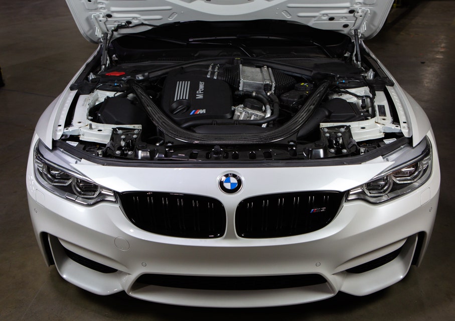
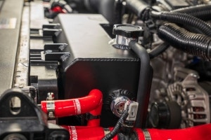
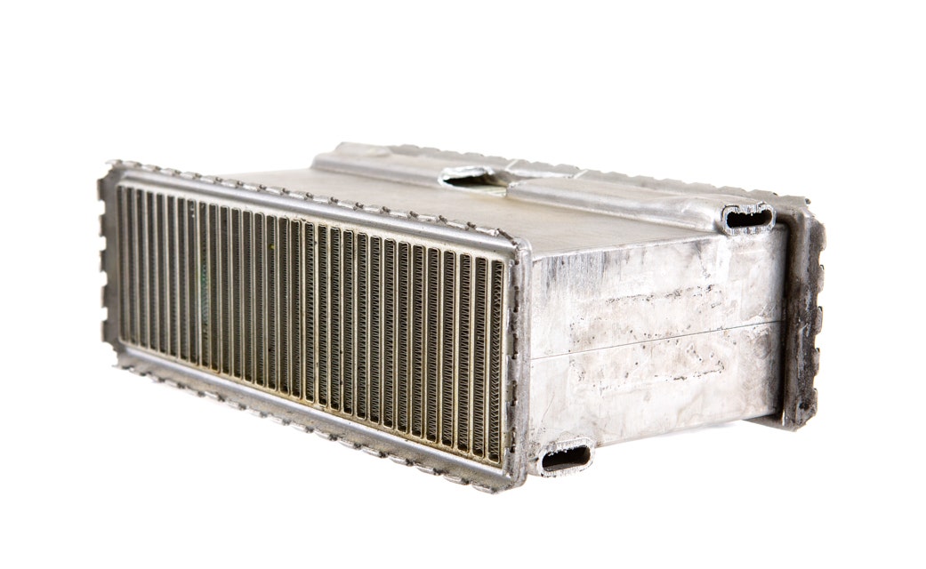
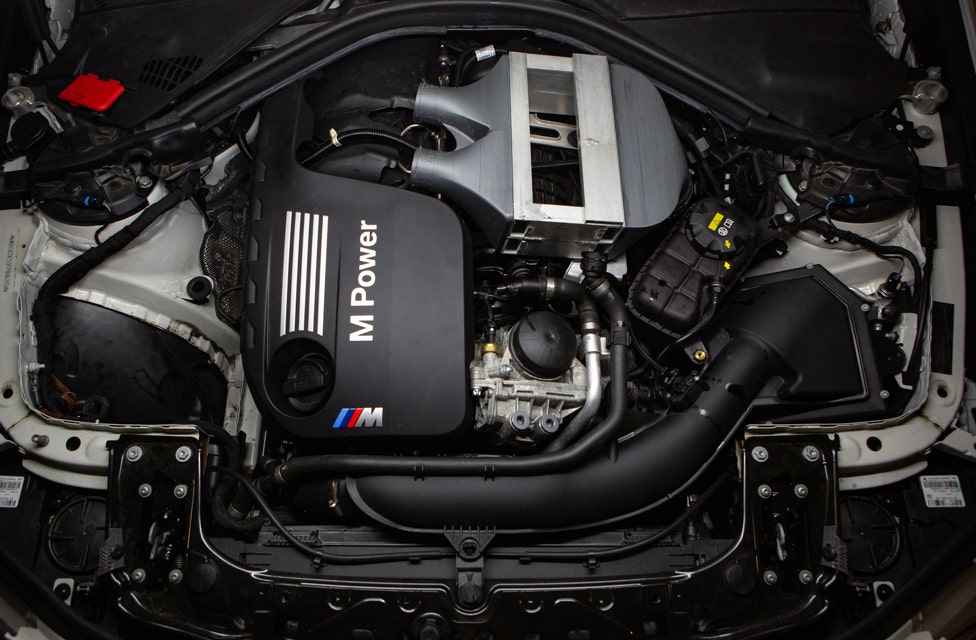
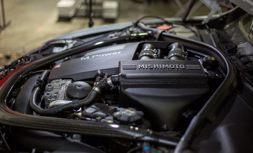
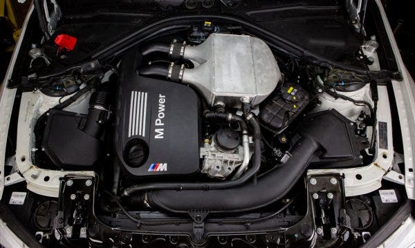
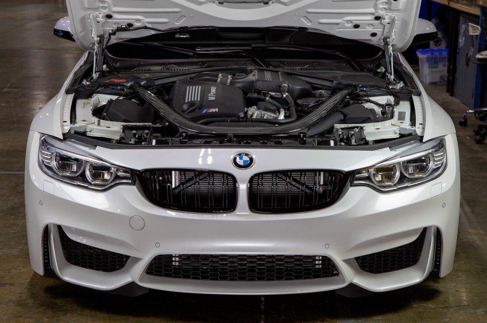
When the F80s started showing up on the showroom floors, and more specifically in the driveways of their new owners, some were left scratching their heads inquiring about the “big silver box” prominently displayed in their engine bay. Thanks to the use of coolant to transfer heat from the charged intake air, the intercooler can be placed in line with the intake manifold, mitigating the extra lengths of hot- and cold-side piping. This small silver box has just about the same cooling power as an air-to-air intercooler three times the size.
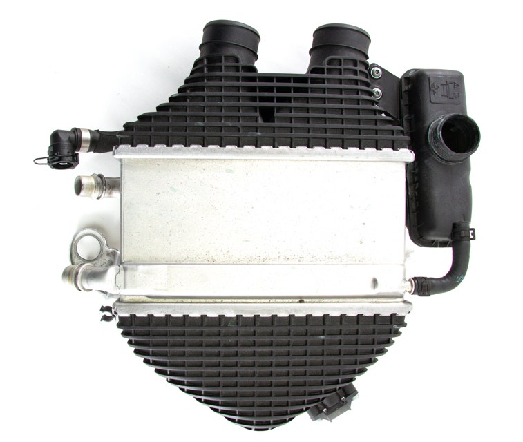
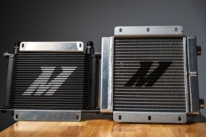
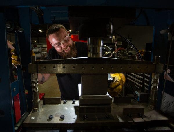
To find out how, we did some exploratory surgery. We started by extracting the intercooler unit from our M3’s engine bay. Once removed from its perch on top of the S55, it’s even more apparent just how small the core is. Measuring in at 10.8”x 5.75” x 3”, the stock core is sporting a 186.3in^3 core volume. For comparison, the intercooler equipped with the N55 (aka the M3’s single-turbo’d little brother) has a core volume of 407in^3. Clearly there’s a reason BMW elected for this intercooling method, so we dug deeper.
The most apparent reason (as described in our heat exchanger post) is that it’s much easier and more efficient to transfer heat to coolant thanks to the thermal conductivity of water. However, there’s a little more to this core than meets the eye, so we pried off the end tanks to take a look.
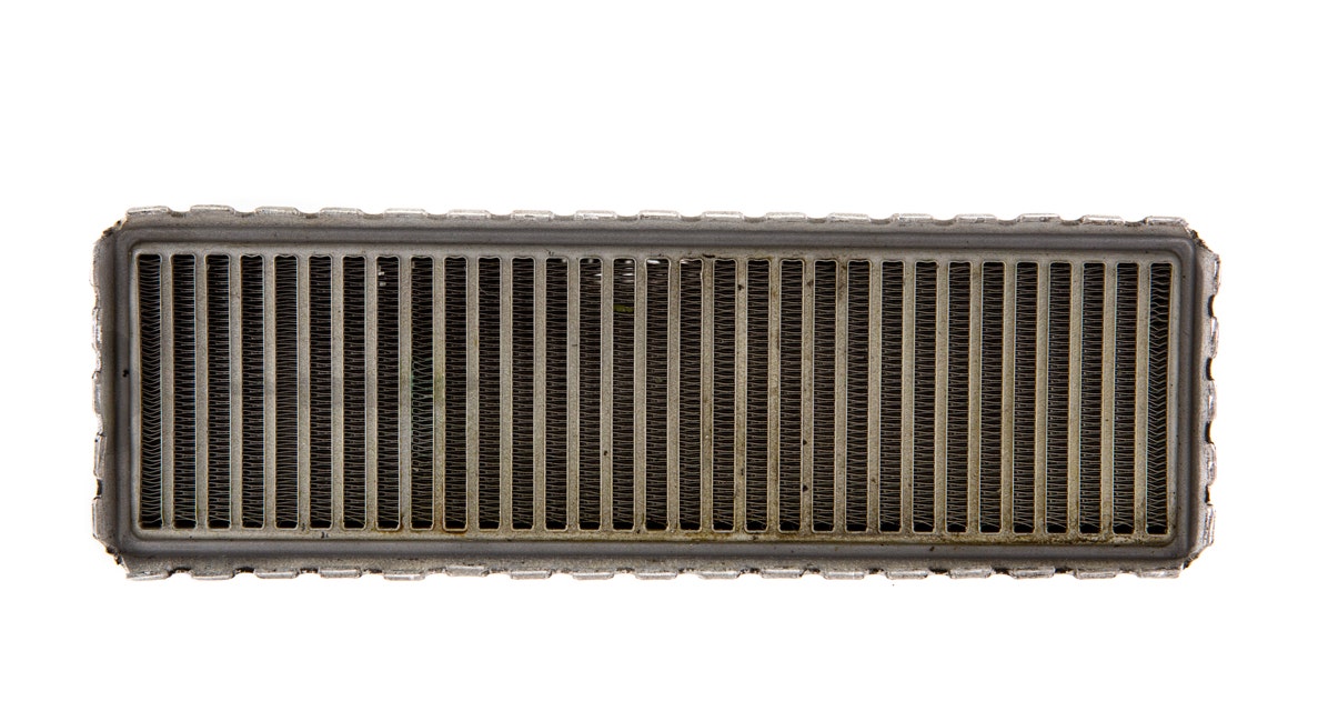
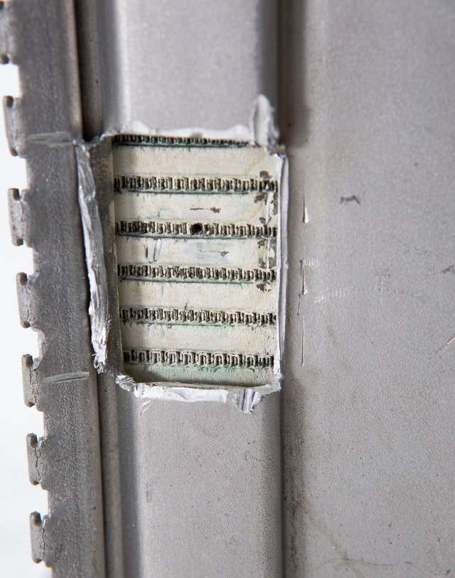
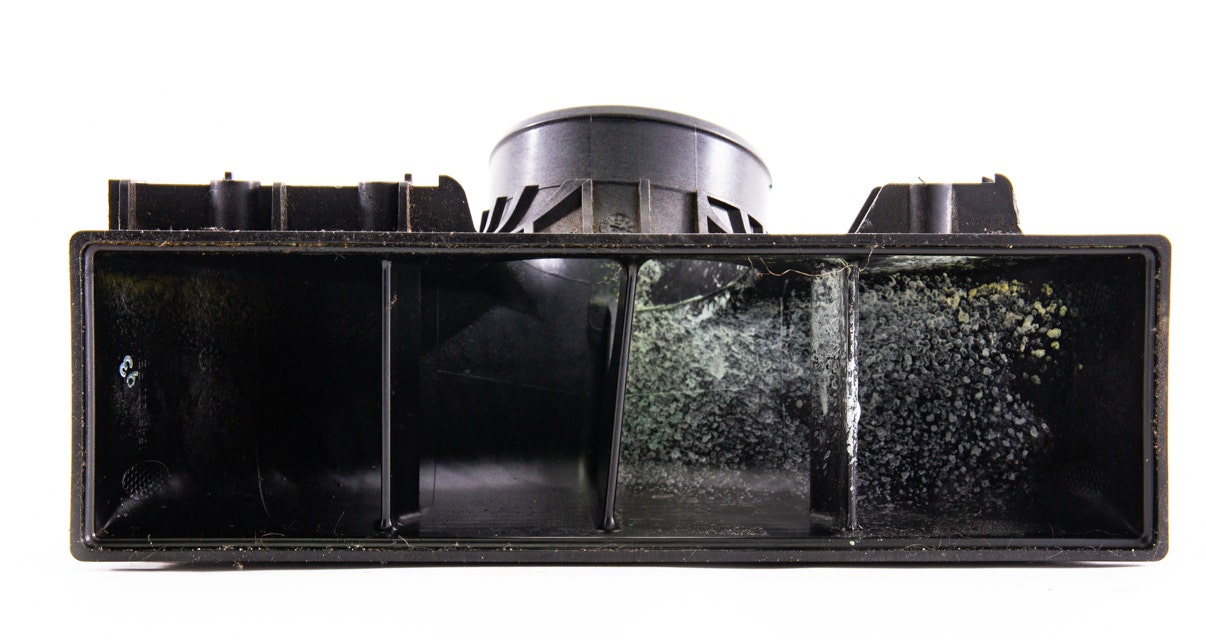
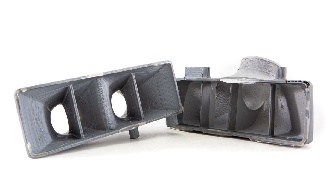
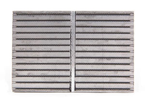
The tubes on the air side of this intercooler are packed with a dense fin design. Essentially, BMW is packing as much of the fin surface area from a traditional air-to-air intercooler inside of this core. By using a tight fin pitch combined with a standard offset fin design, the charged air has plenty of contact with the fins and effectively transfers the heat to the coolant.
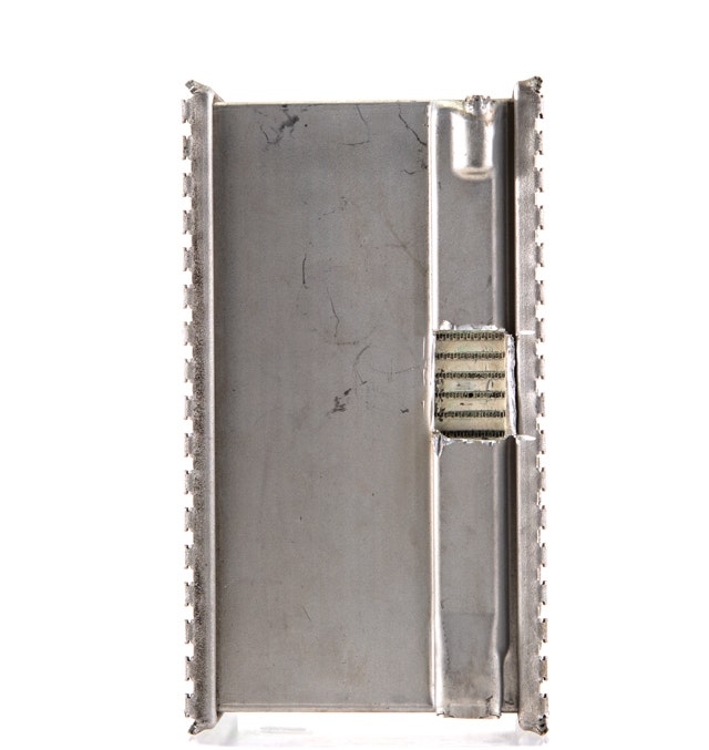
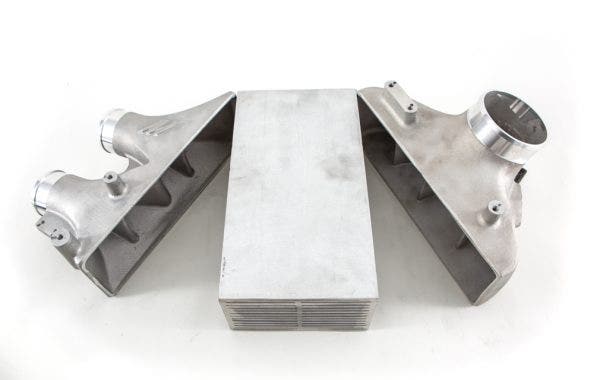
BMW funneled the coolant’s flow through the intercooler in an interesting fashion. The inlet, or cold-side for the coolant, is injected at the top right corner of the core and across via a channel on top of the housing. From there it’s squeezed across the core via ducts just under the housing. Finally it trickles down and across to the outlet located on the bottom left side of the core.
BMW funneled the coolant’s flow through the intercooler in an interesting fashion. The inlet, or cold-side for the coolant, is injected at the top right corner of the core and across via a channel on top of the housing. From there it’s squeezed across the core via ducts just under the housing. Finally it trickles down and across to the outlet located on the bottom left side of the core.
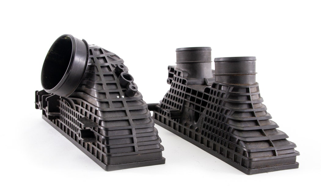
While we had the intercooler disassembled, we took a closer look at the end tank design. For starters, they’re constructed from plastic, which is ideal for mass production but prone to leaks and cracks.

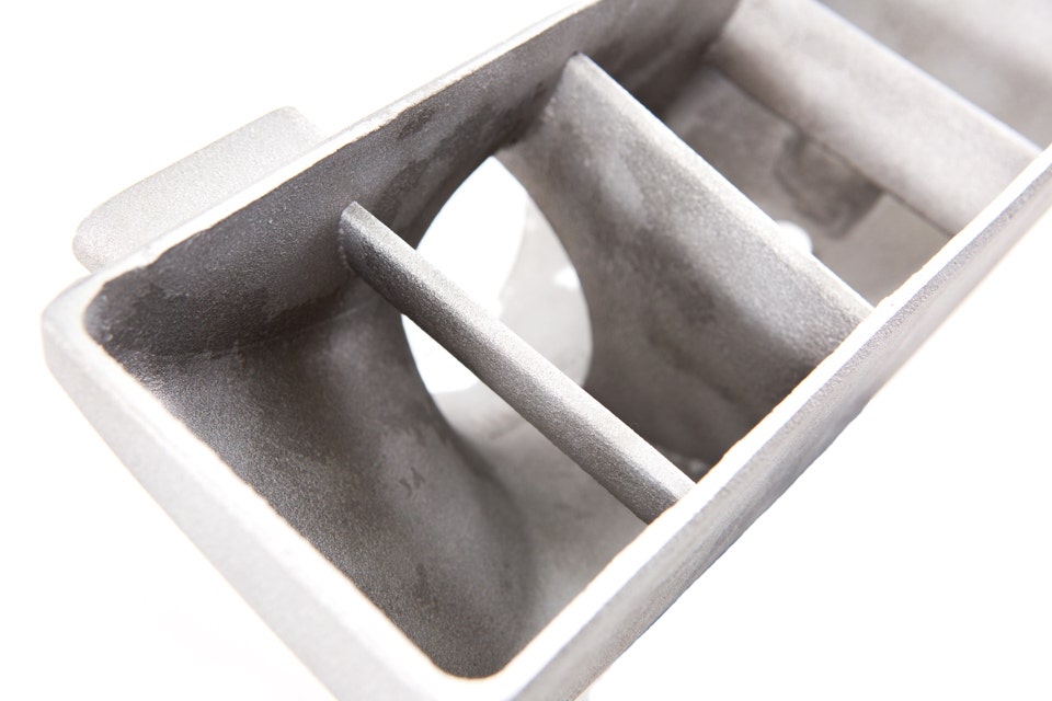
A peek inside the tanks is a visit to diverter city. When using this small of a core, it’s imperative that every single square millimeter is used. For that reason, BMW incorporated an internal diverter on both hot-side inlets to ensure an even spread of air flowing into the core, making full use of every densely packed fin. A feature we intend to keep in our design.
When we look inside the cold-side end tank, we see a similar story with how the air is straightened before entering the intake manifold. Combined with the general shape, these internal diverters are strategically placed to reduce the airflow’s turbulence as it passes into the throttle body to reduce pressure loss.
Done with Downsizing
While the future is about downsizing, we still see some room to grow when it comes to the F80’s air-to-water intercooler. Since the intercooler isn’t in the direct path of the airflow anymore, the size of the core can be a fraction of what it used to be. However, the old adage still rings true—bigger is better.
The first task on our to-do list is to give the core some extra muscle. The concept of transferring heat (though it’s to coolant in this scenario) is the same. The more condensed fin surface area we can cram in there, the better. Our design is going to bump the core size up to 241.5in^3, equating to a 29% increase in size over the stock unit.
Next item, coolant flow. There are two options when it comes to how we route the coolant through the core. The first is to retain the same path, which is to have it trickle through the channels via a duct on the top and bottom. The alternative would be to feed the coolant directly through the front and set up a dual pass system. It’s tough to determine the ideal coolant path at this stage, so in the name of science we plan on testing both. Make sure to check out the caption below for a more in-depth look on the dual pass core layout.
Final items are the end tanks. BMW laid an impressive foundation for us when it comes to the end tanks. Basically, there wasn’t much to improve on other than making the necessary adjustments to fit the larger core. Sure, these initial fitment prototypes are still plastic, but that’s just representative of the planned cast aluminum construction. Diverter city is not being evicted, but rather updated. Both the hot- and cold-side tanks will retain similar diverter designs in order to keep the charged air flowing smoothly through the system.
A Whole New Cool
With our assessment complete and the fitment confirmed, it was time for Jason to put his design plans in motion. Sure, the real beauty of this new intercooler design is the internal layout, but we couldn’t help ourselves when it came to the outward appearance as well.
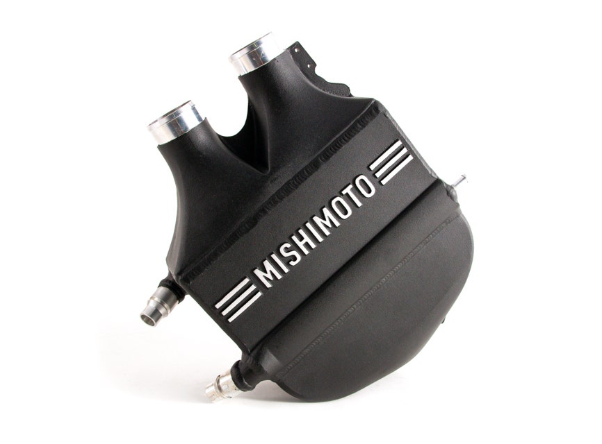
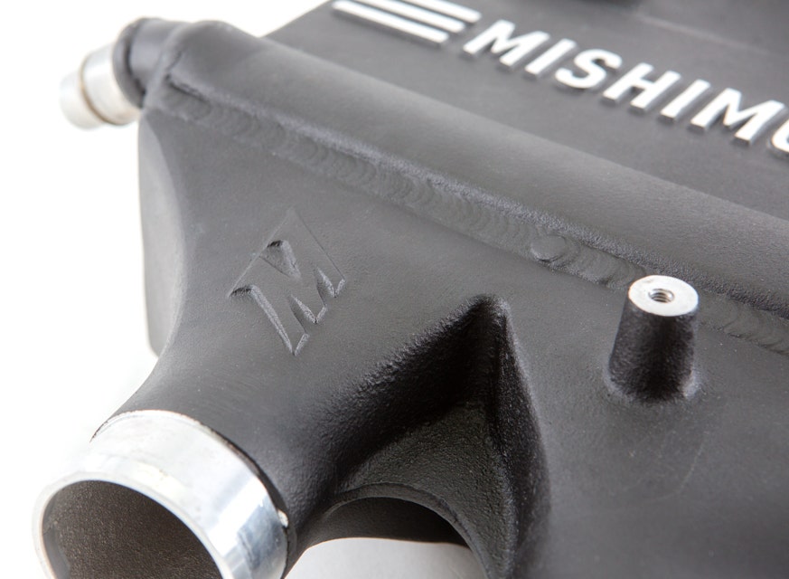
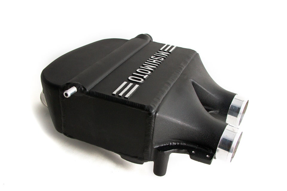
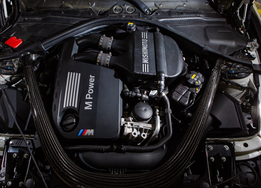
The first noticeable feature is the cohesive design with the M’s engine bay. The stock unit is unsightly and sticks out like a sore thumb. While we wanted ours to be noticeable, we didn’t want it to clash. Drawing from BMW’s styling ques, our engineer carried over the same theme on the top and bottom plates of our intercooler, looking right at home in the bay.
The beauty is more than just skin deep. On top of expanding the core size, we had two different possible paths on the layout of internal coolant fins. We wanted to ensure that we were doing our due diligence determining which was best for the S55, so we made sure that we had one of our single pass, crossflow cores and fabricated a dual pass intercooler here in-house.
-
It starts with the core. We derived this core from our Ford Power Stroke design but tailored it to fit both physically and functionally with the S55. -
We had a set of our end tank castings sent in specifically for fabricating up our dual pass intercooler. -
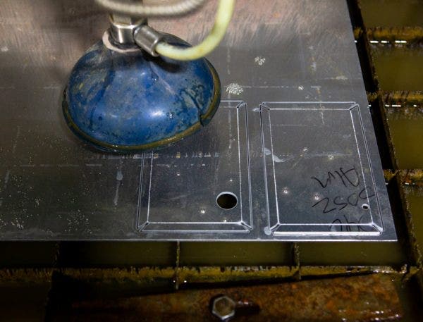
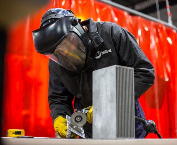
Using our water jet, our in-house fabrication expert, Mike, whipped up a pair of plates to help direct the coolant through the intercooler. -
Making some adjustments for the perfect fit. -
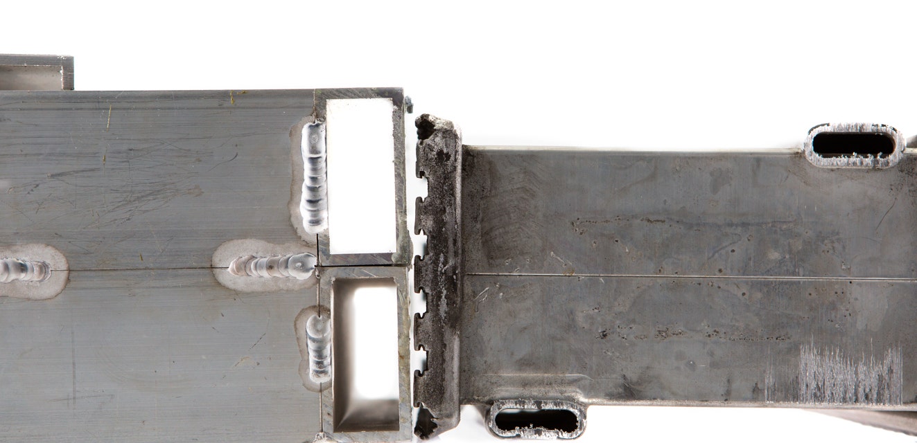
Some more fine-tuning to the header plates. If you look closely, you can see the diverter plate, which keeps the coolant flowing in the correct direction. -
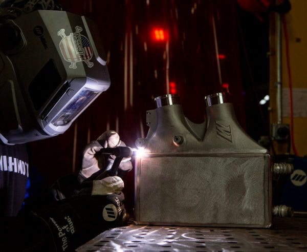
We missed out on the welding shots for the heat exchanger, but we were able to get them in for this part of the project. -
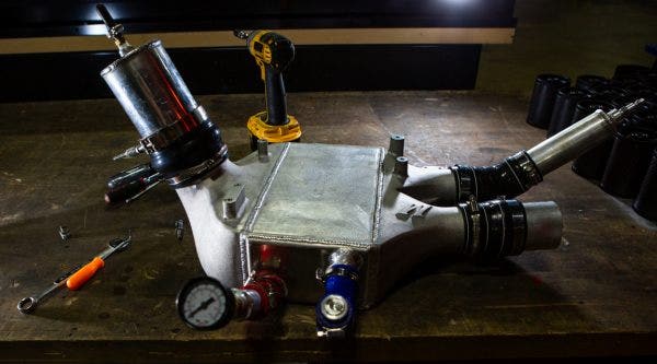
Pressure testing to make sure that both the air and coolant don’t seep out of any welds. -
Ready for testing.
Both these core designs follow the paths laid out above, but with our new single pass design, we made sure to adjust the layout of the internal coolant fins in order for a more efficient passage of the liquid through the core. With the stock layout, the coolant is essentially playing a game of Plinko to squeeze from one side to the other. This means of coolant passage could potentially stay in the core too long and start transferring the heat back to the charged air. By creating a more streamlined path through the core, we’re establishing an environment for more consistent and effective cooling.
The coolant side of the core is only half of the story. Ensuring the air side of the fins are up to snuff is just as important. The stock core uses a tightly packed offset fin design, which is the same formula that we also used, but the larger core means that we could make some adjustments. More space allowed us to still use the offset fin layout, but with a slightly looser fin pitch, all while increasing the volume of fins. These improvements combined mean a 16% increase in the airflow through the core. This stat that will come in handy once we get to the dyno.
Speaking of airflow, this new core would practically be worthless without the means of shepherding the charged air through it. Since BMW already laid a sturdy foundation, there wasn’t too much Jason needed to change for our end tanks. Updates were needed nonetheless. For starters, plastic is out and cast aluminum is in. This new manufacturing process means a much more reliable air passage to and from the core. The main update in shape comes from the intercooler’s outlet. We gave the interior of this end tank a bit more of a curve for a smoother flow of air into the intake manifold, which contributes to the improved flow.

Group Effort
In case you haven’t already figured it out, air-to-water is a team sport. The intercooler is reliant on the heat exchanger to dissipate the collected heat in order to properly cool the charged air. For that reason, we were primarily interested in pitting the results of our system against the stock layout during the test. In addition, we also know that most owners looking to upgrade their intercooling system are doing so because of a tune, so we ran all our tests with a Stage 1 map to compare the systems.
We are primarily monitoring three main attributes to determine the effectiveness of each system—power, intercooler coolant temperatures, and the intake air temperature. In order to capture this data, we split the testing into three different sections which help pinpoint each set of data more accurately.
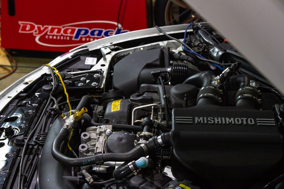
First up, the intercooler coolant temperature. This figure is the foundation of the results, meaning that by improving the cooling capacity there’s also a positive effect on IAT and power. This also specifically points to how well the heat exchanger performs within the system. To collect this data, we performed a load test with our M3 on the Dynapacks in which the vehicle is put into 4th gear, and then held at 4000RPM for 30 seconds. This puts the M3 under a heavy load to make sure that the intercooling system is working its hardest throughout the test.
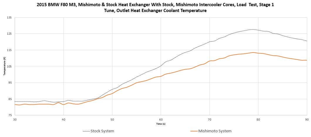
Through this two graph we were able to decipher the heat exchanger’s performance as well as the total cooling power of the system. First, by comparing the data between the inlet and outlet at the 70 second mark, we saw a 25°F drop in coolant temperature across the core. That’s 6°F better than the stock unit. With just our heat exchanger installed, we were able to lower the global system coolant temperatures by 10°F and an additional 3°F once our intercooler was in the mix. 10-13°F might not sound like much, but with the coolant temperatures consistently lowered, it means for more efficient heat transfer from the charged air.
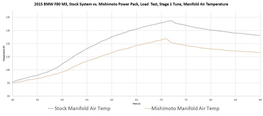
With the coolant temperatures dropping, we were able to see the effect on the air passing through the intercooler. We also measured the temperature of the air entering the intake manifold both after the stock and our intercooler during the load tests. From the same 70 second mark in the test, we recorded a 12°F drop in the intake air temperature after the installation of our intercooler.
The missing piece to this puzzle is: What do all these improvements lead up to? Sure, extra power is one thing, but the better and more consistent cooling for your Bimmer’s intercooler system means a solid platform for even more modifications. But yeah, the power too.
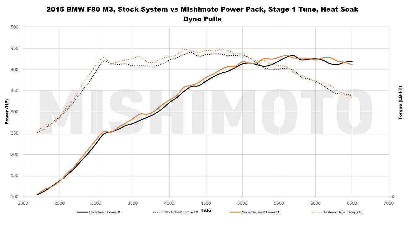
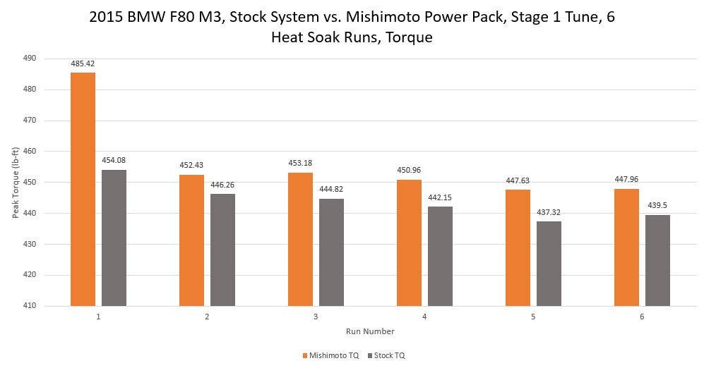
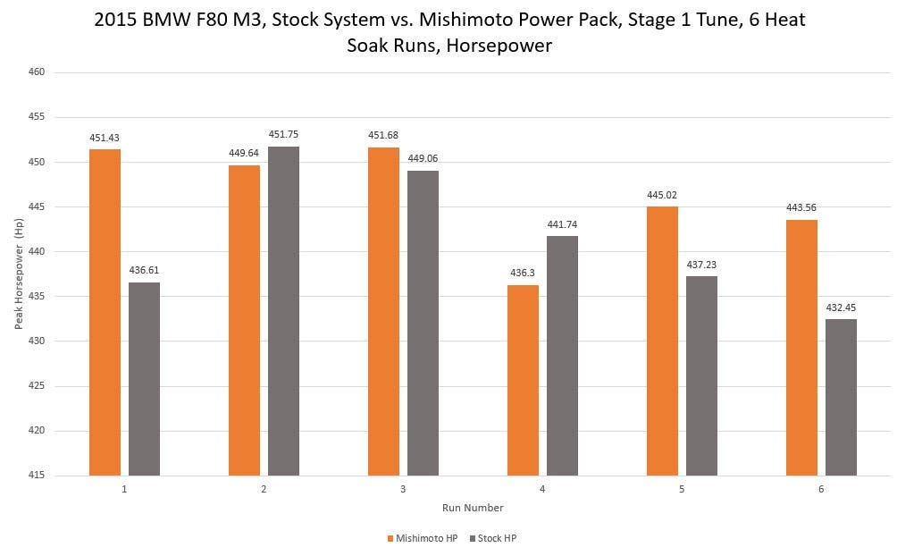
Collecting a consistent power figure on the M3 proved to be a little tricky. Essentially, the horsepower and torque numbers shifted depending on the heat soak in the system, so there were inevitably some outliers. Sure, we could have just plopped the fattest horsepower gain here and called it a day, but we’re not about cooking the books. Instead, we recorded our power figures over a series of six consecutive dyno pulls, similar to one of our heat soak tests, and averaged them together. This way we’re collecting not only a more consistent set of data, but also simulating a real-world result. We were able to record an average 3–5 gain in horsepower and 2–10 boost in torque on top of the gains from the tune, with a peak of 31 horses and 10 ft-lb. across the series of runs.
We performed all these tests side by side with our dual pass core design, as well collecting similar results in each experiment. We ultimately decided to move forward with the single pass core design since it allowed for more internal fin volume, and we saw an improved flow equating to more potential heat rejection.
Perfection Powered
When it comes to sports sedans, the M3 is as close as you can get to the perfect balance between carving corners and soaking up the highway. BMW did have a few shortcomings when it came to the latest iteration of the market’s benchmark, but we here at Mishimoto made sure to reinforce the weak spots so the F80 could keep its title as the Ultimate Driving Machine.
Make sure to stock up on all your M3 and M4 performance needs, available now:
2015-2020 BMW F8X M3/M4 Performance Air-to-Water Intercooler
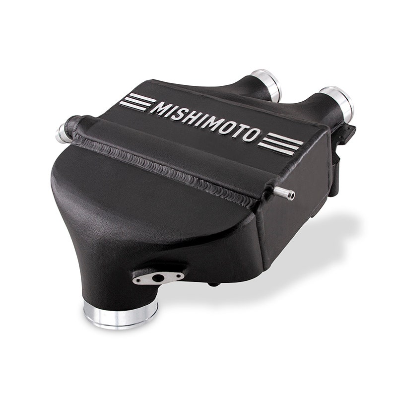
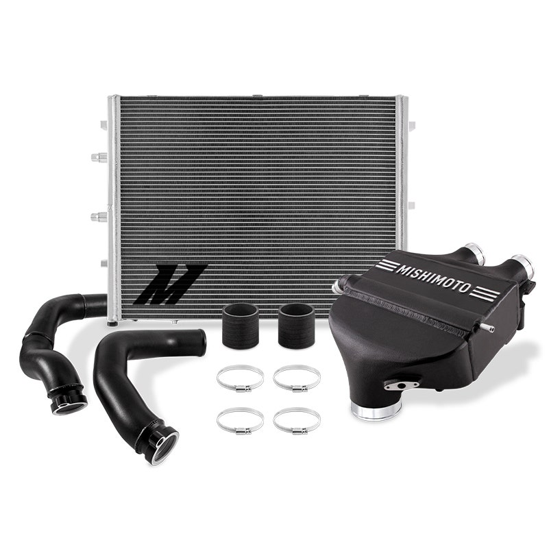
2015-2020 BMW F8X M3/M4 Air-to-Water Intercooler Power Pack
Thanks for Reading!
-Nick