A New BMW F30 Performance Intake, Part 2: Airbox Fabrication
Interested in purchasing our F30 intake system? Check out our product page for more information!
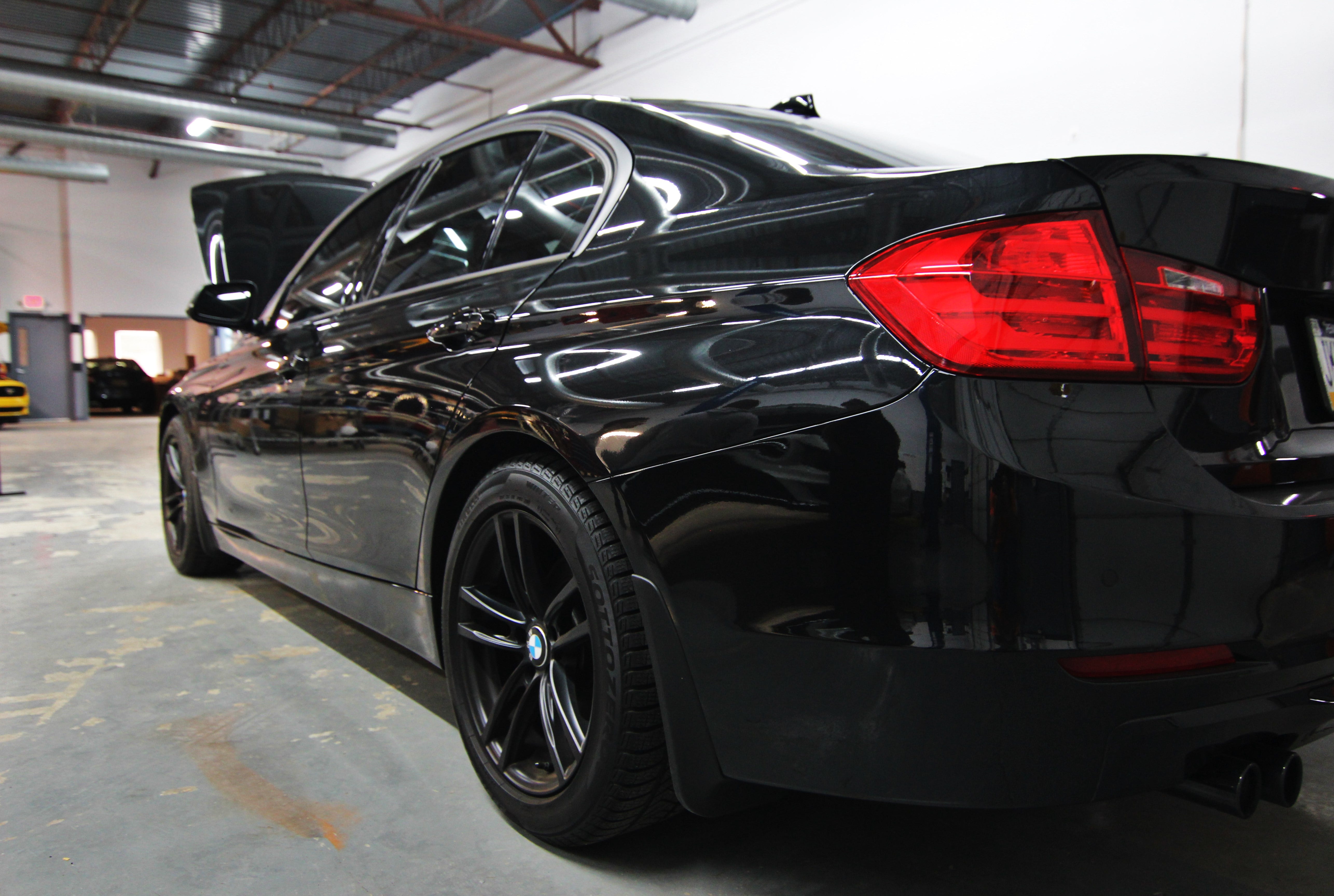
Mishimoto BMW F30 Performance Intake!
Time for an update on our F30 intake project! Check out the continued progression of our development below!
Airbox Base Fabrication
We left off last time with the completion of our intake pipe fabrication that leads to the airbox. Next on the list: assembling our airbox and refining the design to the appropriate shape we wanted to achieve.
We started with the base of the box, which will be utilizing the factory air duct to acquire a cool stream of airflow.
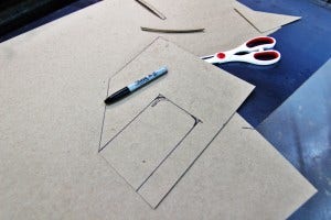
Airbox base cardboard template
A few bends and we had the basic shape in steel form.

Airbox base fabrication
Open up the argon tank and fire up the Miller! This piece was tacked up and fit into position on our test vehicle.

Airbox base fabrication
We decided to make this a two piece box, differing slightly from our other airboxes. Typically, our boxes comprise a dual piece unit, but the lid is just a single flat face. In this design, we were a bit creative and opted to go with a large lid that mounts to the base with discreet hardware.
To start this design we added a mounting edge to our existing base as well as a hole for the intake tube to pass through. Check this out mocked into position with and without the air filter installed.

Airbox base fabrication
Notice our use of weather-stripping around the pipe inlet to reduce the chance of noise from vibrations.

Airbox base fabrication
Once fitment was perfected, this unit was fully welded.

Airbox base fabrication

Airbox base fabrication

Airbox base fabrication
Airbox Lid Fabrication
Next we needed to fabricate the lid for this box. This piece would slide over top of the base and would be secured into the rivet nuts shown on the base. We tackled this component in a different fashion than usual. The design was first modeled in Solidworks and then transplanted onto paper templates to be cut and bent into shape. For complex components with multiple bends, this makes the fabrication process far quicker.

Airbox lid fabrication

Airbox lid fabrication
Once tacked together, a large portion of our initial prototype was complete. Check it out!

Airbox lid fabrication
Here's a look at this setup installed in our test vehicle!

Fabricated airbox installed

Fabricated airbox installed

Fabricated airbox installed
Airbox Bracket Fabrication
One of the last features needed for this airbox system was a form of support to hold the box in position. We used a peg on the passenger side to fit into the stock grommet mount. An additional point toward the driver side of the box was needed for additional rigidity.
We started brainstorming ideas for the design of this bracket and came up with some cardboard templates.

Mounting bracket templates

Mounting bracket template mock-up
After reviewing our options, we went with a more square design to match the contour of the box itself. Below is our printed template ready for bending, cutting, and shaping.

Mounting bracket template mock-up
The basic shape was cut, bent, and placed into position!

Mounting bracket template mock up
We then made a few modifications to the box mounting points and bent up our final prototype.

Mounting bracket fabrication

Mounting bracket fabrication
Gussets were then added to provide improved strength and rigidity for this mount, and we bolted up our final bracket.

Mounting bracket fabrication

Mounting bracket fabrication
Coming Next!
Now that we had our final prototype mocked up, we needed to conduct some product testing to evaluate how this intake sounds and performs on our dynamometer.
Check back soon for our testing results and a video compilation of our dyno runs!
Thanks
-John
