2021+ BMW G8X M3/M4 Intercooler MMINT-G80-21 Engineering Report
GOAL: Create a direct-fit performance intercooler that outperforms the stock intercooler.
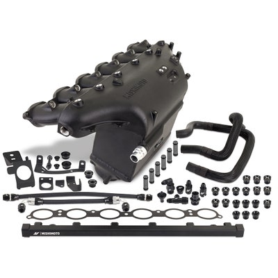
RESULTS: The Mishimoto manifold outflowed and outperformed the stock intake manifold while decreasing the pressure drop through the manifold. The Mishimoto manifold is more reliable than the factory manifold by replacing the crimped-on intercooler core with a fully welded aluminum core. In addition, the Mishimoto core is approximately 33% larger than stock and flowed up to 15% better than the stock manifold.
CONCLUSION: The Mishimoto intercooler kit is a great upgrade for those looking for more power and reliability for their S58-powered BMW.
Design Objectives:
-Create an intercooler that performs better than the stock intercooler
-The intercooler must give the customer the ability to add port fuel injection and port nitrous injection. *
-The intercooler/manifold must not increase pressure loss through the system.
-Must be direct-fit and bolt to the engine in place of the stock intake manifold.
Stock System Overview:
When building an aftermarket part that improves upon the factory part, first, the stock system must be evaluated. The secondary cooling system in the G8X BMW is likely the best factory air-to-water system on any vehicle we have tested. During initial dyno testing on our 2021 M3 Competition in stock configuration, we saw peak intake air temperatures that were less than 10 degrees over the ambient temperature with only a 2-3 degree (Fahrenheit) temperature rise during pulls, all while consistently making 500 horsepower at the wheels. Even more impressive, we were able to perform 6 dyno runs in a row while maintaining peak power within 1.5% of the first run, indicating the system’s ability to stay consistent run after run. (typically 2-4% is normal)

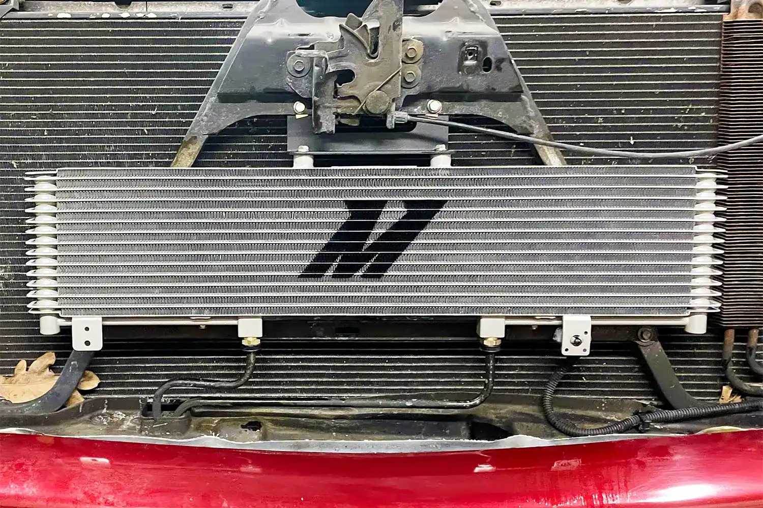
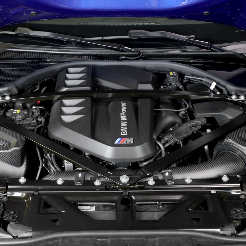
To give a quick overview of the intercooler system of the S58 engine, the intercooler is built into the intake manifold, between the throttle body and the runners. Water flows through this intercooler and then into a heat exchanger (radiator) in the front of the car that cools the water down so that it can flow back into the intercooler and continue to remove heat from the air moving through it. This is called secondary cooling since the intercooler cools the air, but the intercooler is cooled by water, as opposed to a primary system, where the charge air is directly cooled by the outside air within the intercooler. As a result, the intercooler is heavily dependent on the performance of the whole system. Generally, when upgrading secondary cooling systems each component must have the cooling and flow capacity to work together as a system to provide optimal performance. In the past, we have found that the most efficient upgrade path for the secondary cooling system may involve replacing a combination of the intercooler, heat exchanger, and water pump, depending on which parts may be leaving performance on the table.
The factory intercooler utilizes a counterflow arrangement between the water and the coolant. This means that the water, freshly cooled down from the heat exchanger enters through the top of the core where it is exposed to the (cooler) air exiting the intercooler, and then exits at the bottom of the intercooler, where the hot air enters the core. This arrangement allows for the maximum temperature difference between water and air, which facilitates quick and efficient heat transfer.

The biggest downfall of the factory system is its construction. The intercooler core is aluminum and crimped onto the upper and lower plenums from the factory. During the design process of this part, there were rumors of M3’s blowing open their intake manifolds after tuning for higher boost pressures. Even more so, BMW released a technical service bulletin saying that some of the intercooler assemblies were improperly crimped during manufacturing, acknowledging that this was a widespread issue, not just a rumor or an anecdote. Our years of experience with automotive cooling systems show that time and time again, plastic tanks crimped to aluminum cores leak and fail. Even if you were one of the lucky ones to receive (by BMW’s account) “a properly made” factory unit, repeated heat and pressure cycles will inevitably lead to a failure. The Mishimoto welded aluminum bar and plate core will be able to handle 60+ psi of boost with no issue and withstand repeated heat cycles from long-term usage.

We have also seen OEM air-to-water intercoolers fail by leaking between the air and water channels inside the core. These internal leaks allow coolant to get into the engine, potentially causing coolant to be burned, engine misfires, or even engine damage. Our strong bar and plate construction helps to prevent this issue. Each Mishimoto air-to-water intercooler core is leak tested on both the air side as well as the water side to provide ultimate reliability.
Finally, bar and plate intercooler cores are inherently stronger and more reliable than a factory tube and fin core. While more costly and slightly heavier, a bar and plate core contains extruded bars, stacked with plates on either side, which are then brazed together. The factory tube and fin cores use thin tubes that are only held in place by the header plates on each side of the core. Our tried-and-true combination of cast end tanks and bar and plate cores prove to be incredibly robust, and we stand behind them with a lifetime warranty.
Another important factor in the design of our intercooler/intake manifold was the integration of port fuel injection and nitrous injection for those looking to use the intercooler for high-power performance. The G8X utilizes direct injection fueling. Like a common rail diesel, fuel is fed into an engine-driven high-pressure fuel pump which feeds high-pressure fuel to the injectors, in excess of 5,000 psi. This fuel is shot directly into the combustion chamber. While it is a great system at stock power levels, the direct injection systems often fail to keep up fuel flow at higher boost and power levels, especially when using E85-based fuels for their increased knock resistance. E85 fuels require an increased fuel volume for the same amount of boost and power. To accomplish this, many enthusiasts implement a supplementary port injection system to provide the extra fuel volume needed at higher boost and power levels. In addition, adding port injection helps prevent intake valve carbon build-up seen in direct injection engines, as the fuel cleans the back of the intake valves.
Design and fitment:
The design of this system was quite complex. There were quite a few design challenges that stood out:
· Increasing core volume while increasing flow
· Ensuring the air flows through the full intercooler
· Maintaining access to the oil filter without manifold removal
· Providing each of the 6 cylinders with even flow
· Creating a port injection system
· Adding direct port nitrous injection
· Preventing heat transfer from the cylinder head into the intercooler
· Maintaining mounting bosses and features of the factory manifold

Fitting a larger core into the same space provides quite a challenge. BMW does an excellent job of packaging its designs. The core was limited in each direction. An A/C line runs past the rear, EVAP lines run past the front, a brace runs across the top, and the throttle body below must stay in the same position to mate to the factory charge pipes. In addition, increasing the height of the manifold will create a sharper turn that the air needs to make as it leaves the core. By mocking up a core in our SolidWorks CAD software, we were able to strike a balance between core size increase and keeping the geometry for proper flow and fitment.
The core used is a bar and plate, air-to-water, single-pass core, designed specifically for this application. The core is very densely packed with both air and water fins while keeping a large ratio of airflow area to heat transfer area. The internal flow area was increased by 24%, which will allow the core to flow more area despite having a dense fin pack. As discussed earlier, the bar and plate core design also provides strength and reliability to the intercooler. In addition, we opted to keep the counterflow arrangement between the water and air, allowing optimal heat transfer between the air and water in the intercooler.


While running a larger core, the incoming air must have the chance to flow through the full core to allow maximum cooling. The inlet of the manifold is biased towards the front of the motor, which, in theory, will push most of the air through the front half of the intercooler core. The intercooler core is most efficient if the full core is being fully utilized. With many design iterations through SolidWorks built-in CFD software, we created an internal diverter in the lower plenum. This diverter helps to push the incoming air toward the back of the intercooler core so that the full core is utilized. Simulations were performed cylinder-by-cylinder to simulate a running engine, where each cylinder takes air from the runners and plenum one at a time, and ensure that each cylinder was able to flow properly.


Another large challenge was increasing the plenum volume and increasing flow while still allowing access to the oil filter housing. The removal and replacement of the intake manifold is a time-consuming task, requiring draining both cooling systems on the vehicle. To solve this issue, the Mishimoto manifold has a cutout, allowing access to the oil filter. This cutout was optimized to be the smallest it can be, minimizing airflow disruption while allowing the oil filter to be removed from the vehicle with the manifold installed.


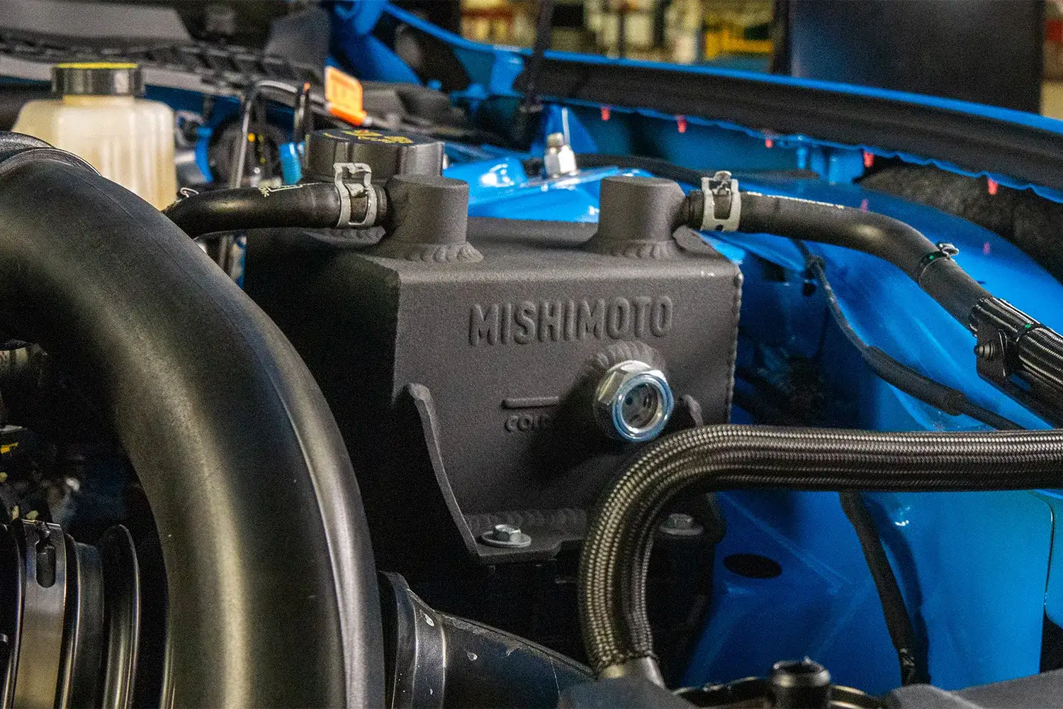
Many other design considerations were taken with the manifold to make it user-friendly, functional, and easy to install. For instance, the manifold includes a billet machined adapter that threads into a boss on the manifold to allow you to use the factory engine cover. We included a threaded boss on the front of the manifold as well as a billet adapter to be able to run the manifold on the X3/X4 M vehicles that use a slightly different EVAP system (as well as a plug for those running a G8X vehicle). The manifold keeps all the mounting bosses to mount the rear wire harness bracket as well as the secondary coolant reservoir. We have even included brackets so that you can use the stock MAP sensor wire clips that keep the MAP sensor wire off the manifold and routed cleanly. We also include custom molded hoses to make sure that all the EVAP lines can be used without stretching or kinking them, ensuring that all emissions-related equipment that interacts with the intake manifold is intact and functioning properly.

In addition, we include a new lower manifold mounting bracket as well as a threaded adapter that bolts into the lower plenum. This arrangement is not only easier to install, but it allowed us to make the lower plenum larger and flow better, which in turn, will allow even flow distribution across the core and better cooling.


As with most manifold designs, runner balance is quite important. If one runner outflows the other runners (or if one runner is significantly weaker than the others) then each cylinder will not be getting the same amount of air. This can cause one cylinder to run rich or lean, potentially creating damage to the engine. The sensors on the engine, specifically the MAP (manifold absolute pressure) and oxygen sensors are only taking averages from either 3 or 6 of the cylinders, so it is hard to tell if one cylinder is not running correctly. Recent technology and modern control systems have figured out how to make this better, however, it still stands that a well-designed intake manifold will have an even distribution of airflow through the runners.
The factory design as well as the Mishimoto design have the air running through the center of the manifold, which would mean that the air would favor the middle cylinders. In addition, the cutout that was needed to clear the oil filter housing would further restrict cylinders 5 and 6.
To ensure proper flow balance, we tested each runner individually on our SuperFlow SF-1020 flow bench with our 3D-printed prototype. During this testing, we discovered that more flow was needed on the outer cylinders, cylinders 1, 2, 5, and 6. The solution was to change the geometry and drop the plenum floor to allow more air to flow to the outer cylinders. Once the flow was balanced on the 3D-printed prototypes, the testing was repeated with the first production sample. At 250 cfm per cylinder, the variation between the lowest flowing cylinder to the average was 1.8%. The average increase in flow per cylinder was 14%. While the cylinder variation was not perfect, the results were great and cylinder variation was not an issue.

At first glance, BMW intended for the factory manifold to accept port injection. Their part features plastic ports for the injectors that are plugged. Converting the manifold requires removing the manifold for precise drilling to ensure fitment for fuel injectors and a fuel rail. Any mistakes in the drilling process can cause fuel leaks or damage the factory manifold. In addition, it requires an aftermarket fuel rail and lines to be sourced. This proved to be an advantage to us in the design process as the factory injector holes are set up to point the injectors at the back of the intake valve, which creates the best air and fuel mixing. The Mishimoto manifold incorporates precision machined injector ports that shoot the fuel directly into the port at the valves. The Mishimoto manifold includes a billet fuel rail, high-quality fittings, and fuel lines to tee into the factory fuel lines. The included fuel lines are PTFE lined, which allows for the use of highly corrosive fuels like ethanol and are capable of the higher fuel pressure modern vehicles run. The system is designed around a standard, easy-to-find Bosch “shorty” injector. In the case that the vehicle will not be using the port injection system, the manifold comes with anodized aluminum injector blanks with Viton O-rings that allow the manifold to be used while maintaining a reliable seal.


Similarly, those running high power often like to run nitrous oxide injection (or NOS) as well. Nitrous injection requires each cylinder to get the same amount of nitrous so that the engine control system can accommodate properly by removing ignition timing universally. It is also beneficial to have the nitrous nozzle pointed in the direction of the airflow. The Mishimoto design allows for the proper injection angle without blocking airflow. Furthermore, by using adapters, the manifold can accept the two most common nitrous injector threads, 1/8” and 1/16” NPT. If necessary, the adapters can be tapped farther down to allow control over the depth the nozzle goes into the airstream. All the adapters and connections on the manifold use a Viton O-ring connection for a reliable seal. Additional adapters are provided to plug the threaded hole for those not running nitrous oxide injection.
When switching from a manifold made from glass-filled nylon to a manifold made from aluminum, heat transfer from the cylinder head into the intake manifold and potentially raise the intake air temperature. Even more so, that heat can get into the intercooler core and reduce its efficiency. To limit heat transfer from the cylinder head to the manifold, we include a fiber-based gasket... The fiber material has a very low thermal conductivity, which will prevent heat transfer between the cylinder head and the manifold During testing, Mishimoto saw that the issue of thermal transfer to the manifold did not have a significant impact on intake air temperatures. When the gasket was used in the real-world driving test, the manifold did not heat soak and our intake air temperatures stayed low. However, the manifold is offered with both the stock O-ring grooves to accept the stock O-ring gaskets as well as the fiber gasket to suit the needs of every customer and vehicle build.
Testing
The Mishimoto manifold was tested on a 2021 BMW M3 Competition X-drive with Mishimoto Intakes, running approximately 32psig of boost. Testing is done in our temperature-controlled facility. Ambient temperatures stayed consistent between 78- and 80- degrees Fahrenheit throughout the testing process. When testing cooling products such as this intercooler, it is especially important to control ambient temperatures to confirm that the changes in temperatures are the result of the product being tested.

Testing Apparatus
Testing was performed on Mishimoto’s AWD Dynojet dynamometer. Data was recorded on an AQ-1 data acquisition system as well as recording OBD-2 data with vehicle-specific datalogging parameters. The AQ-1 was used to collect pressure data while the OBD-2 data was used using the factory sensors on the vehicle. The vehicle has a temperature and pressure sensor in the charge pipe before the intake manifold and a TMAP sensor (temperature and manifold absolute pressure) sensor in the intake manifold. Unfortunately, this factory sensor was limited to around 22psig of boost so a 5-bar capable AEM sensor was placed in the intake manifold. Our AEM sensor allowed us to read boost pressures above 22psig accurately.
Mishimoto employs a 10hp axial fan controlled by a variable frequency drive (VFD) to provide cooling to the vehicle during testing. The fan is mounted on a hydraulic lift that allows us to position the fan directly in front of the vehicle, providing 60+ mile-per-hour airflow to the many heat exchangers on the front of the G80 M3. The purpose of this setup is to accurately simulate driving in real-world conditions in addition to providing consistent and reliable cooling during testing. In addition, the manifolds were swapped from the vehicle without removing the vehicle from the dyno or moving the fan. We take testing very seriously here at Mishimoto to ensure accurate and reliable results.

Testing Results
Several different tests were conducted. The first test was the single dyno run test. The vehicle was run on the dyno at approximately 32psi of boost up to redline. Before the test, the car would sit on the dyno with the fan on until the vehicle reached a steady state of both intake air temperature as well as coolant temperature. In addition, we monitored the full boost curve from each run to ensure that the actual boost levels were consistent across both manifold tests. It is important to look at the full boost curve, and not simply read the peak boost levels, to ensure that any differences in power and temperature could be attributed to the different manifold. The test was repeated with the Mishimoto manifold with the stock O-ring gasket as well as the Mishimoto fiber gasket. We found no significant difference in the data between the O-ring gasket and Mishimoto gasket in this specific test.
We found that the Mishimoto manifold lowered the post-intercooler intake temperatures compared to stock by about 5 degrees and dropped the pressure drop across the core by nearly 2psi. In addition, we were happy to see that the intake air temperatures were well controlled. At ~80-degree indoor temperatures (climate-controlled shop) the temperatures were within 25 degrees of the ambient temperature, even on back-to-back runs, which is very impressive for an air-to-water intercooler system.


In addition, a heat soak test was performed. Generally, during this testing, Mishimoto will perform 5-6 dyno runs back-to-back. Unfortunately, the vehicle would go into limp mode for an unknown reason after 2 dyno runs. The limp mode issue was not caused by the Mishimoto manifold, as it was first encountered with the factory manifold installed. However, this data still showed a significant difference in intake temperature at the end of two runs of about 4 degrees lower post intercooler intake air temperatures with the Mishimoto manifold.
After reviewing the data and power charts, we found that the vehicle power and torque were inconsistent from run to run. The Mishimoto manifold gained power and torque in some areas, but it was quite inconsistent despite consistently having lower temperatures and pressure drop. It would heavily depend on how much knock the knock sensors would pick up. With more data review, we concluded that the factory turbos were simply being pushed past their limit. The vehicle was making more than 700 horsepower at the wheels. The turbo outlet temperatures were approaching 310-315°F by the end of the run. This means that the intercooler system was tasked with lowering the temperature by over 200°F. Simply put, the turbos were flowing more air than they were designed to do efficiently. This creates issues with exhaust backpressure and lowers engine efficiency, which explains some of the inconsistencies that we saw.
At this point, the vehicle was retested at a lower boost level. We theorized that at a lower boost level, the vehicle would be more consistent, and the data would be more meaningful. Although the lower boost level significantly lowered the peak torque, the vehicle only lost about 10 horsepower with nearly 5 pounds of boost removed. As expected, lowering the boost levels allowed the turbos to operate more efficiently and create less heat. The peak turbo outlet temperature (pre-intercooler) lowered by almost 30°F to 285°F.
Nonetheless, we saw a similar result at lower boost levels. The peak (post intercooler) intake air temperatures were about 2°F lower with the Mishimoto manifold, however, for most of the run, the temperatures were within 1° degree of each other. The Mishimoto intercooler/intake manifold was able to lower peak intake air temperatures and pressure drop while making the same amount of power and torque. The turbochargers would have to be upgraded with larger wheels rated at higher flow rates than the factory turbochargers to flow more air and make more power efficiently. The Mishimoto intake manifold’s increased flow and cooling power would make it a suitable candidate to handle high power while keeping temperatures well in control.

Real World Testing
In addition to dyno testing, we also performed testing on the vehicle in a real-world environment. Our goal was to determine how the aluminum intake manifold would handle the vehicle idling and moving in traffic. We created a test loop around Mishimoto headquarters with a variety of conditions: frequent stoplights, mild traffic, and highway driving. The vehicle was driven “normally” without any excess throttle. The test was performed with the included gasket. The test vehicle for this test was a 2021 G80 M3 Competition RWD with a factory tune and Mishimoto Intakes. This test, along with putting many miles on the vehicle outside of testing, ensured that the manifold did not cause any leaks, check engine lights, or drivability issues.
The temperatures stayed in control quite well. Throughout the 25-minute drive, the intake air temperature never went more than 25 degrees above ambient temperatures and was within 11 degrees of ambient at one point. As predicted, the highest temperatures were seen after sitting at a stop light and getting up to speed and the lowest temperatures were seen during highway driving. Like an air-to-air intercooler, the cooling power is highest when the vehicle is in steady motion to cool down the heat exchanger in the front of the vehicle, which in turn, will cool the intercooler.

Conclusion
The G8X M3/M4 has a great secondary cooling system. Adding the Mishimoto intake manifold/intercooler is a great addition to squeezing every ounce of power out of the S58 engine by combining lower pressure drop across the core and lower intake air temperatures. It is an ideal choice for those going for big power, those who want to add port injection, and/or those who want to add nitrous injection*. The aluminum bar and plate core welded to cast end tanks are built tough and will add reliability to the vehicle. We stand behind this intercooler with Mishimoto’s lifetime warranty.
*Use of the included fuel rail is optional and for race-use only. The fuel rail has a tamper-proof sticker and may be removed only if the vehicle will no longer be used on the street or highway. Check local emissions regulations before removing.